ENGINE PERFORMANCE
4.2L
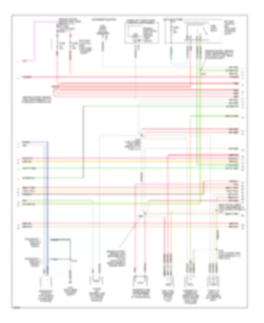
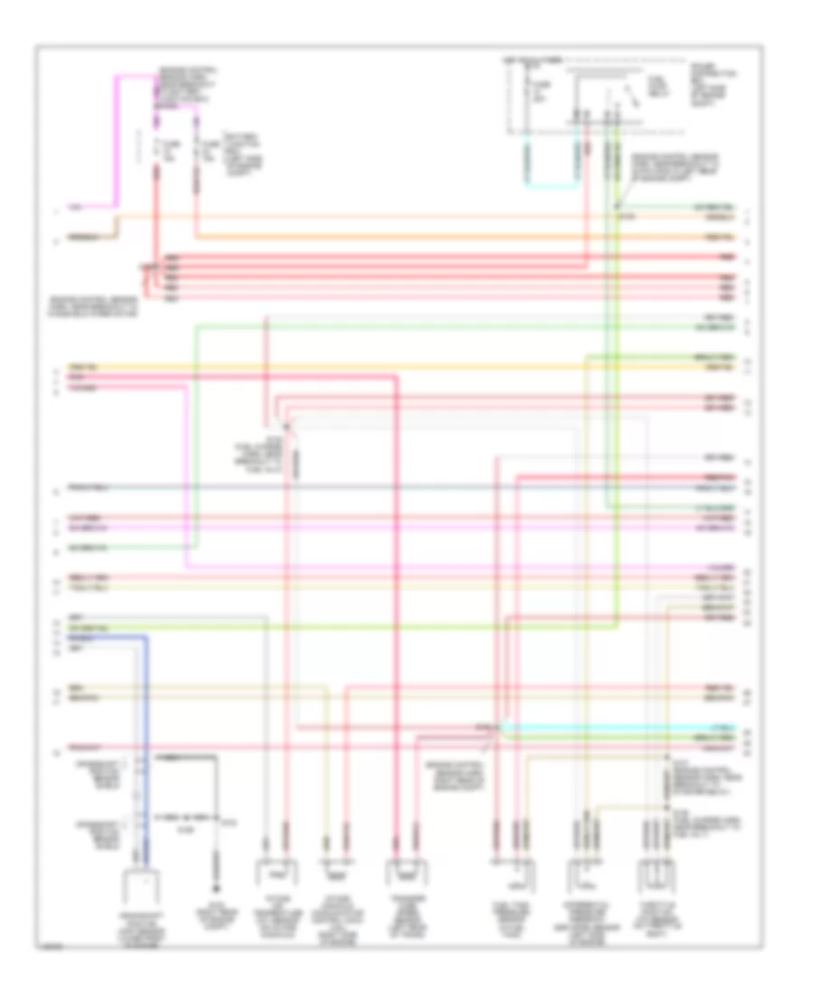
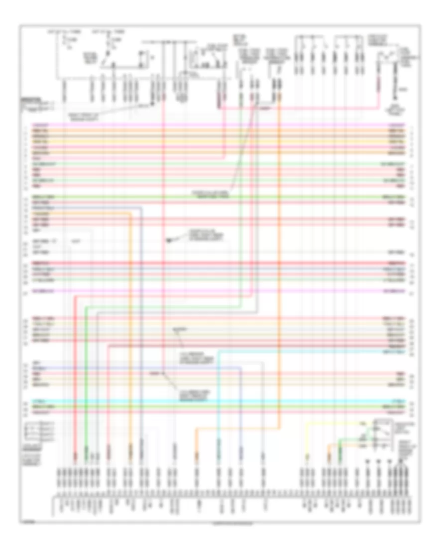
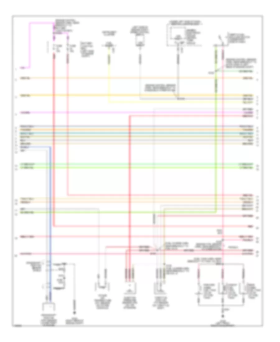
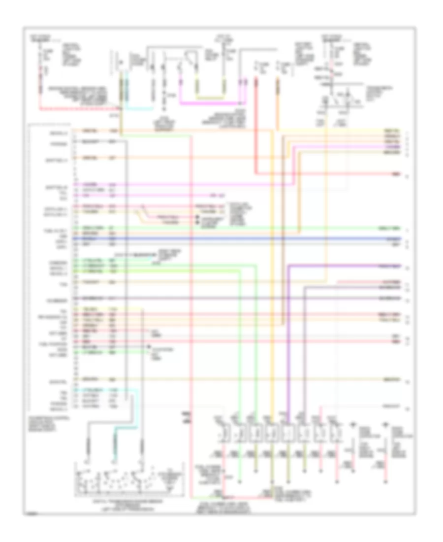
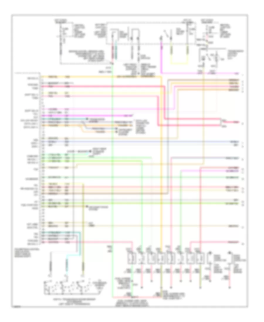
4.2L, Engine Performance Wiring Diagrams (1 of 4) for Ford Pickup F250 Super Duty 2000

List of elements for 4.2L, Engine Performance Wiring Diagrams (1 of 4) for Ford Pickup F250 Super Duty 2000:
- (left front radiator support)
- (rear of right fender apron)
- (right rear of engine compt)
- 4x4 low sw
- 820 ohms
- A/c system
- Accs
- Battery junction box (left side of engine compt)
- Body computer system
- C243
- Case gnd
- Central junction box (under left side of dash)
- Ckp(+)
- Ckp(-)
- Data link (+)
- Data link (-)
- Data link connector (partial) (under center of dash)
- Digital transmission range sensor (dtr sensor) (left side of transmission)
- Dlc
- Evr ctrl
- Fuel pump mon
- Fuse 30a
- Fuse 5a
- G105 (2001)
- G105 (right rear of engine compt)
- G108 (2000)
- G123
- Ho2s (12)
- Hot at all times
- Hot in run or start
- Iat
- Ign coil 1
- Ign coil 2
- Ignition coil
- Imrc
- Instrument cluster system
- Intake manifold runner control (imrc) (on right side of engine)
- Ks sensor
- Maf
- Nca
- O/d off
- Pcm power diode
- Pcm power relay
- Powertrain control module (pcm) (right side of engine compt)
- Pwr gnd
- R n
- Radio noise capacitor 1 (on top of engine)
- S100
- S106 (or s105)
- S116
- S117 (fuel charge harn, near breakout to iac valve)
- S153
- S225
- Shift sol a
- Shift sol b
- Tcs
- Tft
- To dtr sensor (diagram 4 of 4)
- Tr1
- Tr2
- Tr4
- Transmission control indicator lamp
- Transmission control switch (a/t)
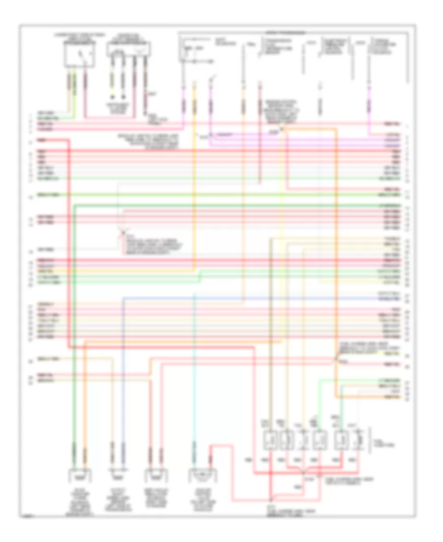
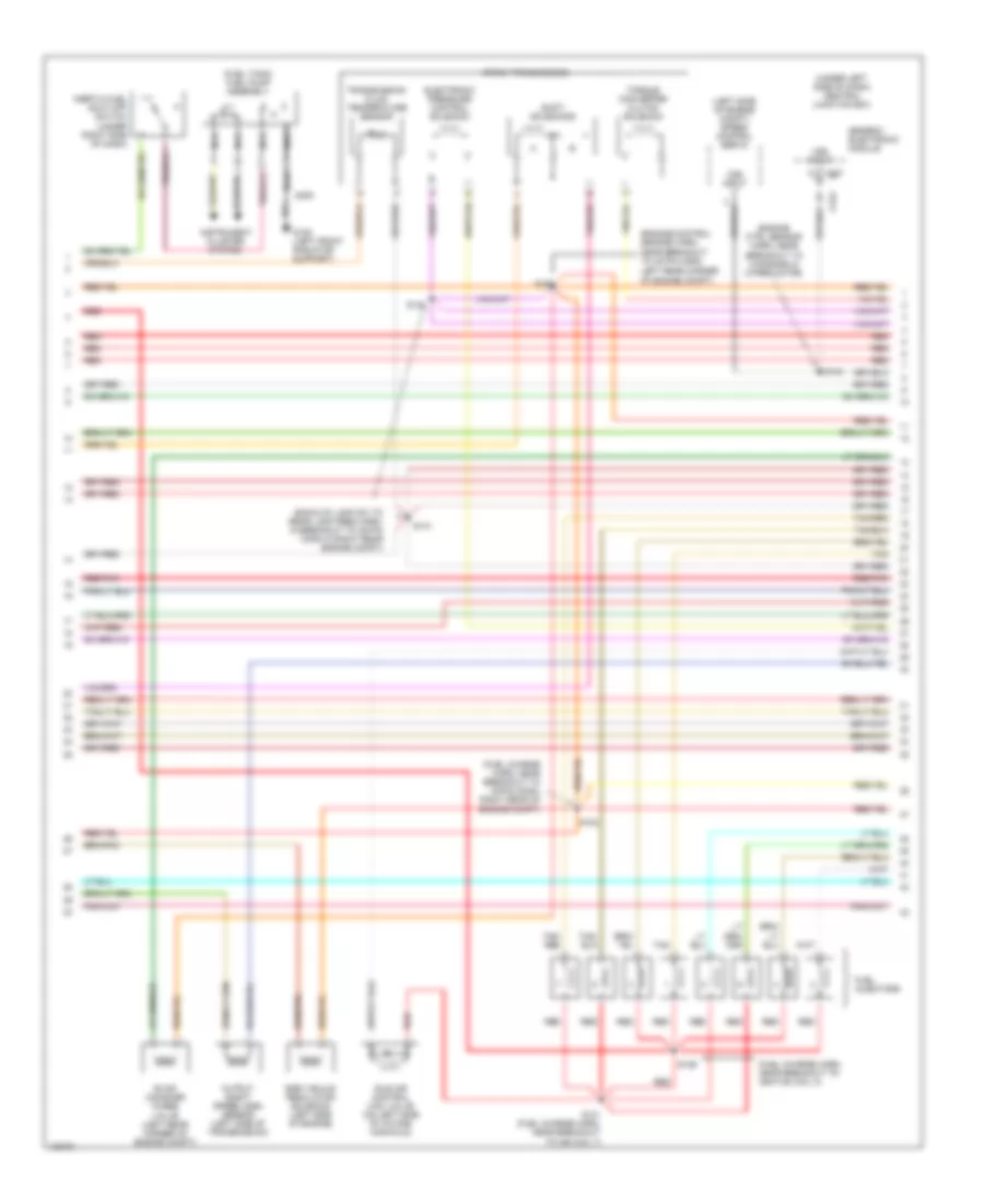
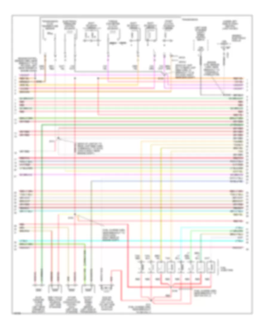
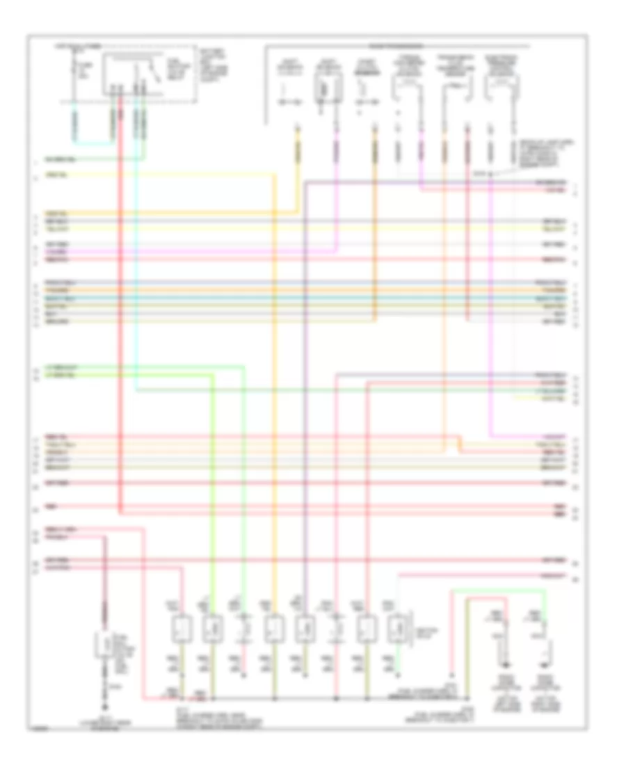
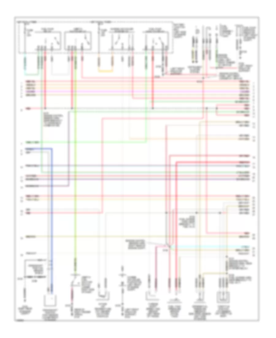
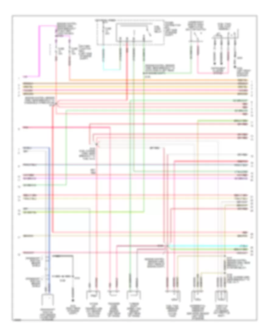
4.2L, Engine Performance Wiring Diagrams (2 of 4) for Ford Pickup F250 Super Duty 2000
List of elements for 4.2L, Engine Performance Wiring Diagrams (2 of 4) for Ford Pickup F250 Super Duty 2000:
- (eng control sens harn, near breakout to starter mtr relay) s137
- (engine control sensor harn, near breakout to 4-pin conn in right rear corner of engine compt)
- (engine control sensor harn, near breakout to 40-pin conn in left rear of engine compt)
- (engine control sensor harn, near breakout to windshield wiper motor)
- (under left side of dash) central junction box
- Battery junction box (left side of engine compt)
- C236
- C267
- Crankshaft position (ckp) sensor (lower front of engine)
- Crankshaft position sensor shield
- Differential pressure feedback egr (dpfe) sensor (right side of engine)
- Fuel pump relay
- Fuel reset switch indicator
- Fuel tank pressure sensor (at fuel tank)
- Fuse 15a
- Fuse 20a
- G123 (right rear of engine compt)
- Generic electronic module/ central timer module
- Hot at all times
- Instrument cluster
- Intake air temperature (iat) sensor (on intake manifold)
- Nca
- Pnk
- Red
- Red/pnk
- S100
- S127
- S135 (fuel charge harn, near breakout to fuel inj 4)
- S136 (fuel charge harn, near breakout to fuel inj 2)
- S138
- S139
- Throttle position (tp) sensor (on throttle body)
- Transfer case speed sensor (at left rear of transmission)
- Vss input
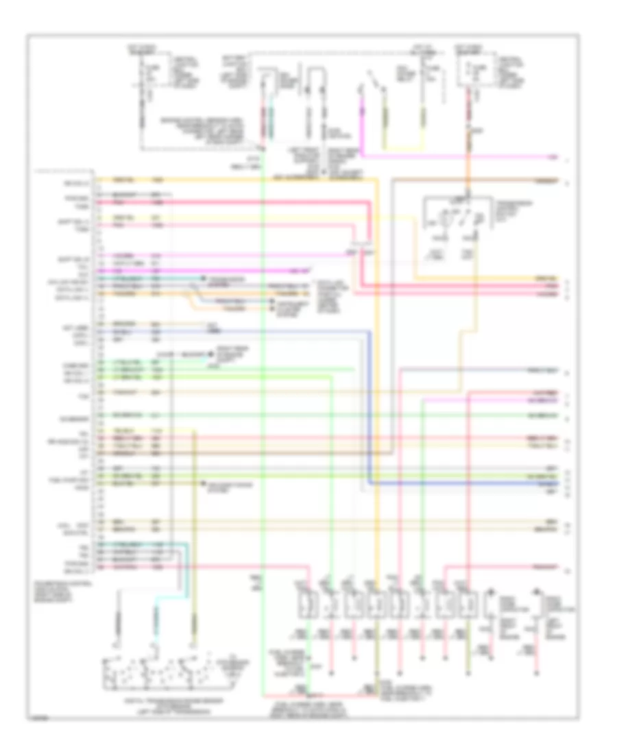
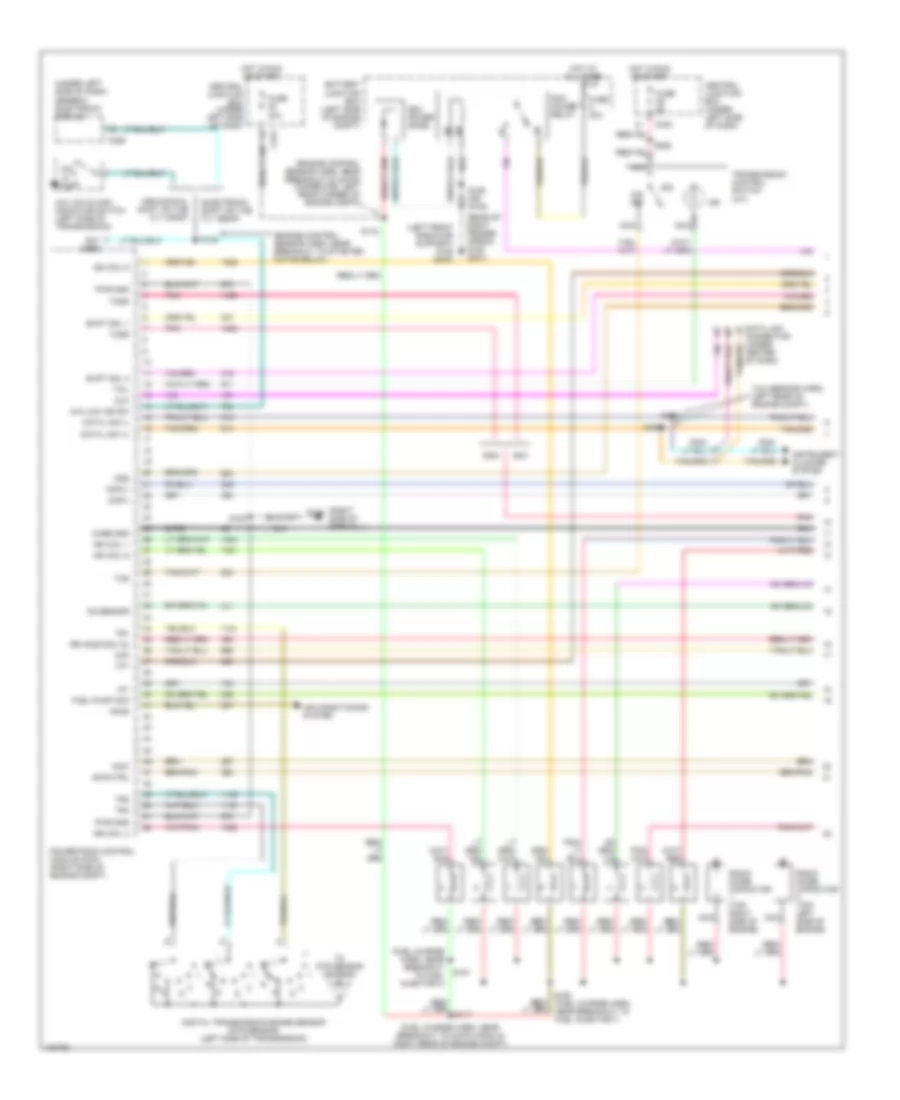
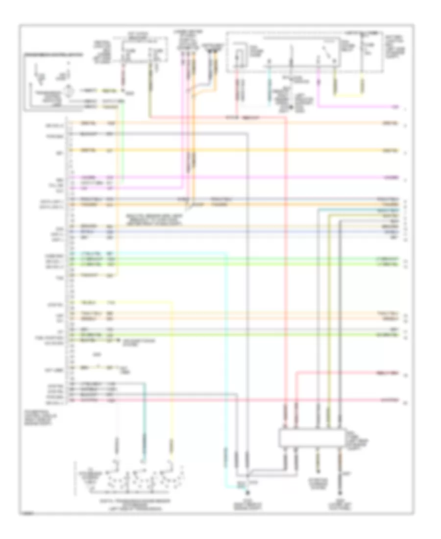
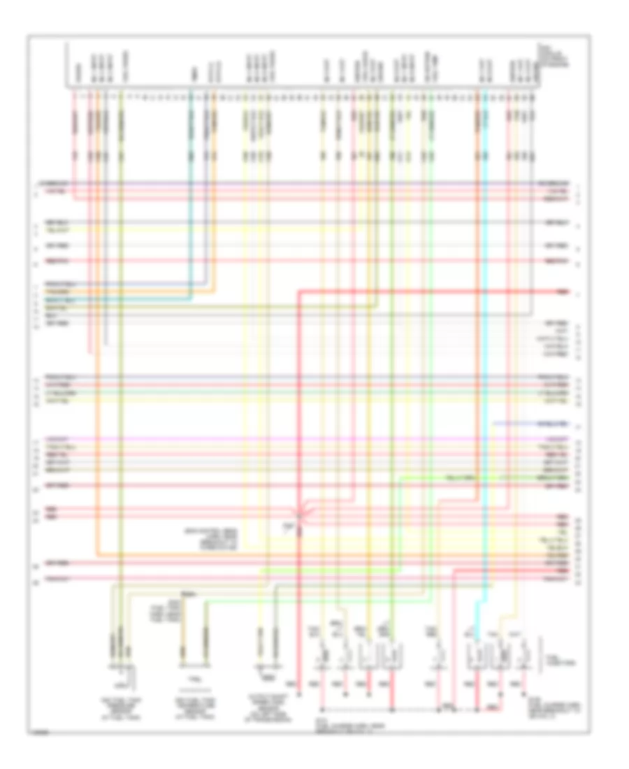
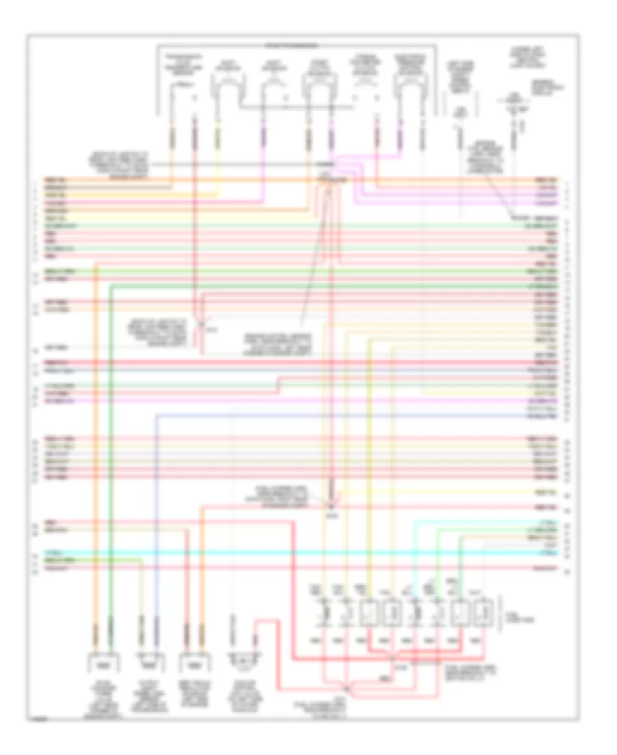
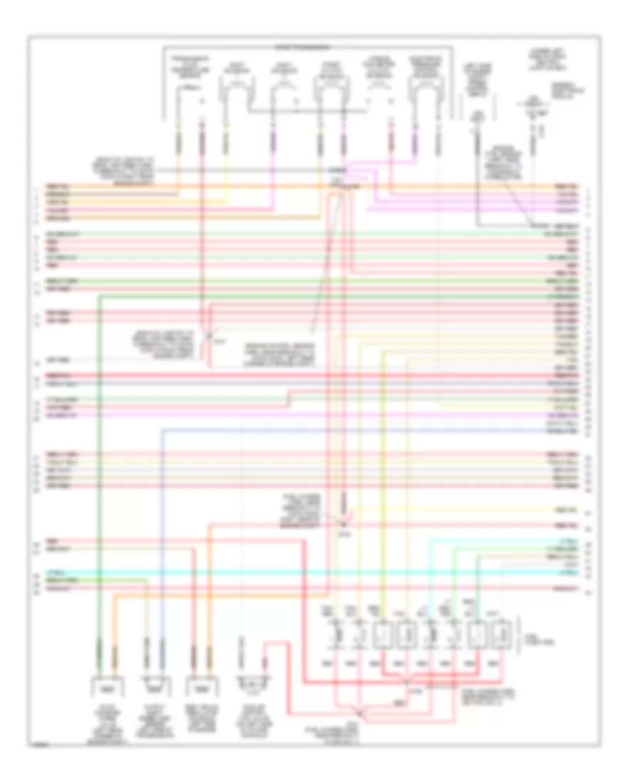
4.2L, Engine Performance Wiring Diagrams (3 of 4) for Ford Pickup F250 Super Duty 2000
List of elements for 4.2L, Engine Performance Wiring Diagrams (3 of 4) for Ford Pickup F250 Super Duty 2000:
- (back-up lamp sw to rear lamp feed harn, at breakout to 38-pin conn in right rear of engine compt)
- (engine control sensor harn, near breakout to 40-pin conn, left rear corner of engine compt)
- (fuel charge harn, near breakout to 16-pin conn, right rear of eng compt)
- (fuel charge harn, near top of cylinder 2)
- (inside fuel pump assembly) fuel pump module
- (under right side of dash) inertia fuel shut-off switch
- 4r70w transmission
- Egr vacuum regulator solenoid (right side of engine)
- Electronic pressure control solenoid
- Evap canister purge
- Fuel injectors
- G200 (left kick panel)
- Idle air control valve (on left side of intake manifold)
- Instrument cluster system
- Nca
- Output shaft speed (oss) sensor (left side of transmission)
- Pnk
- Red
- Red/pnk
- S129
- S131 (fuel charge harn, near breakout to imrc)
- S140
- S141 (back-up lamp sw to rear lamp feed harn, in breakout to 38-pin conn conn in right rear of engine compt)
- S154
- S155
- S207
- Shift solenoids
- Solenoid (left rear corner of engine compt)
- Ssa
- Ssb
- Tan
- Torque converter clutch solenoid
- Transmission fluid temperature sensor
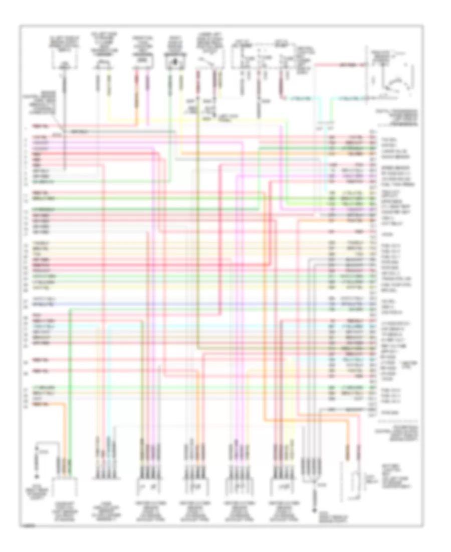
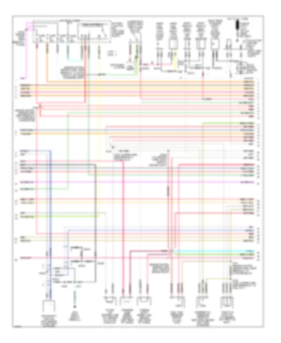
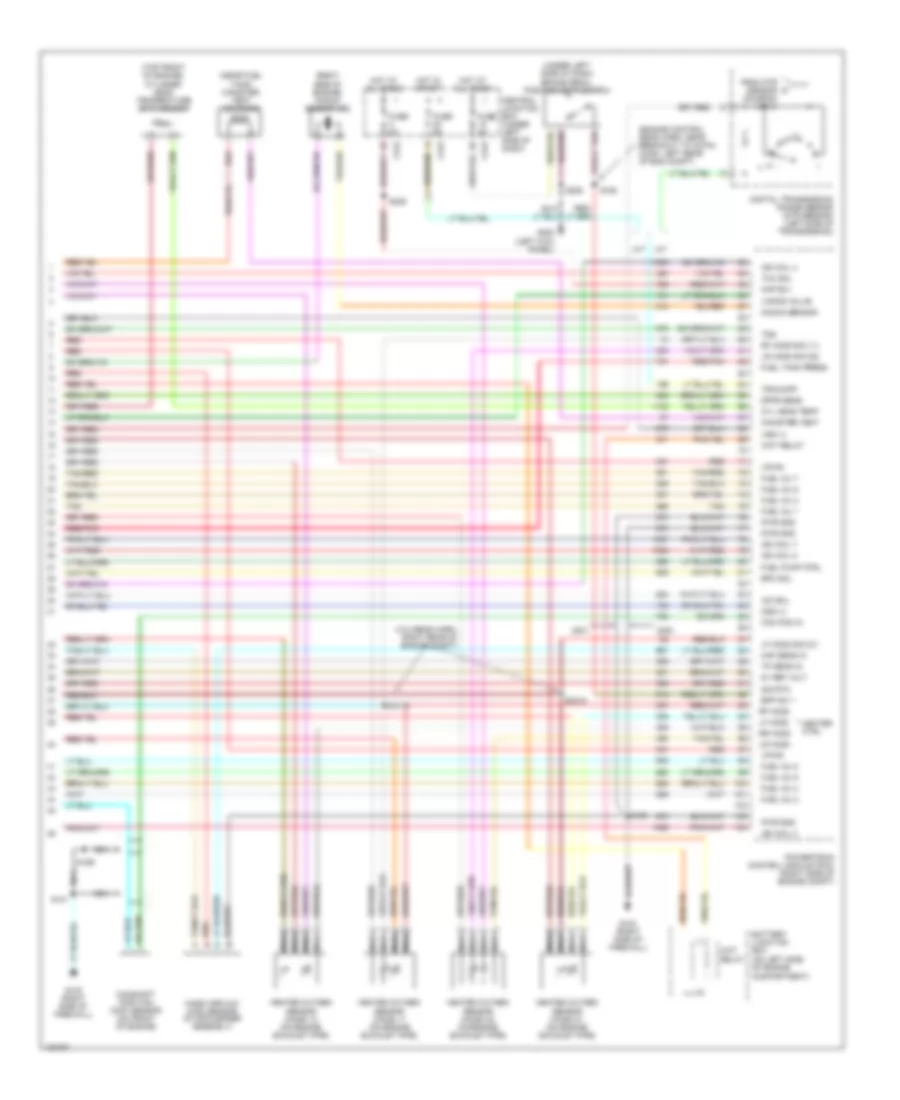
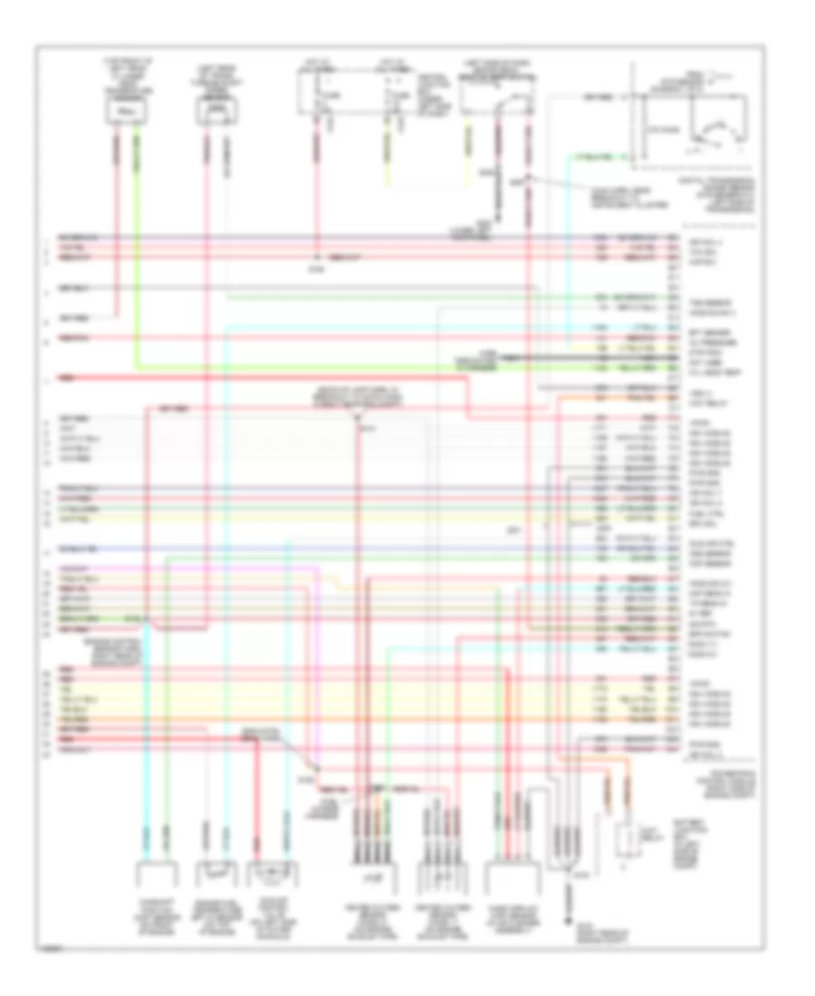
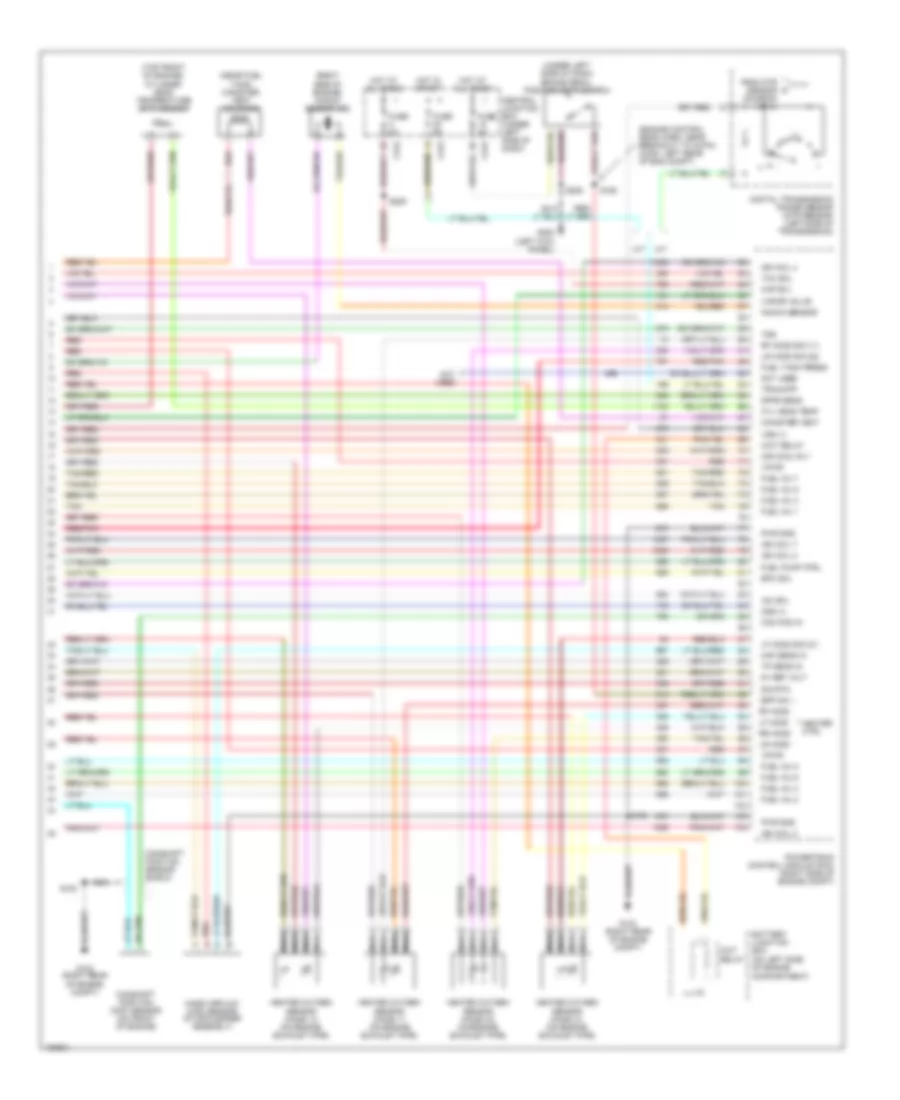
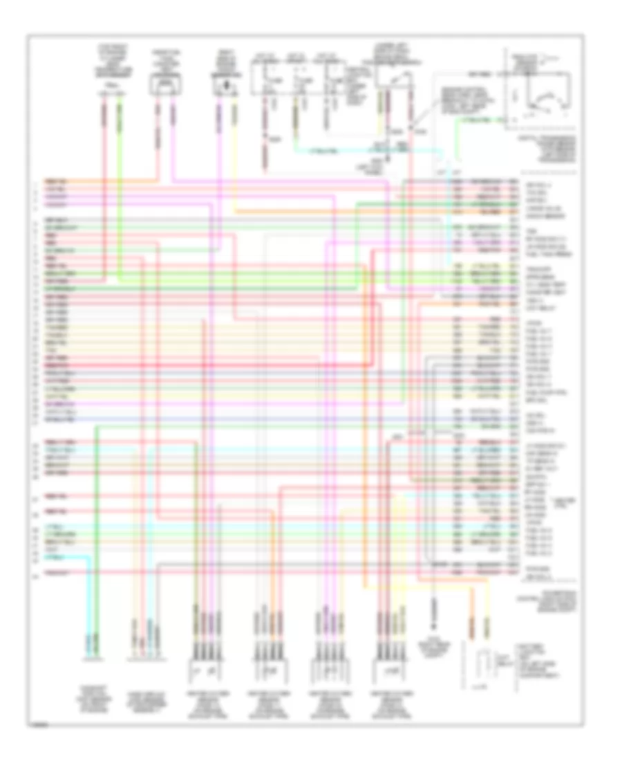
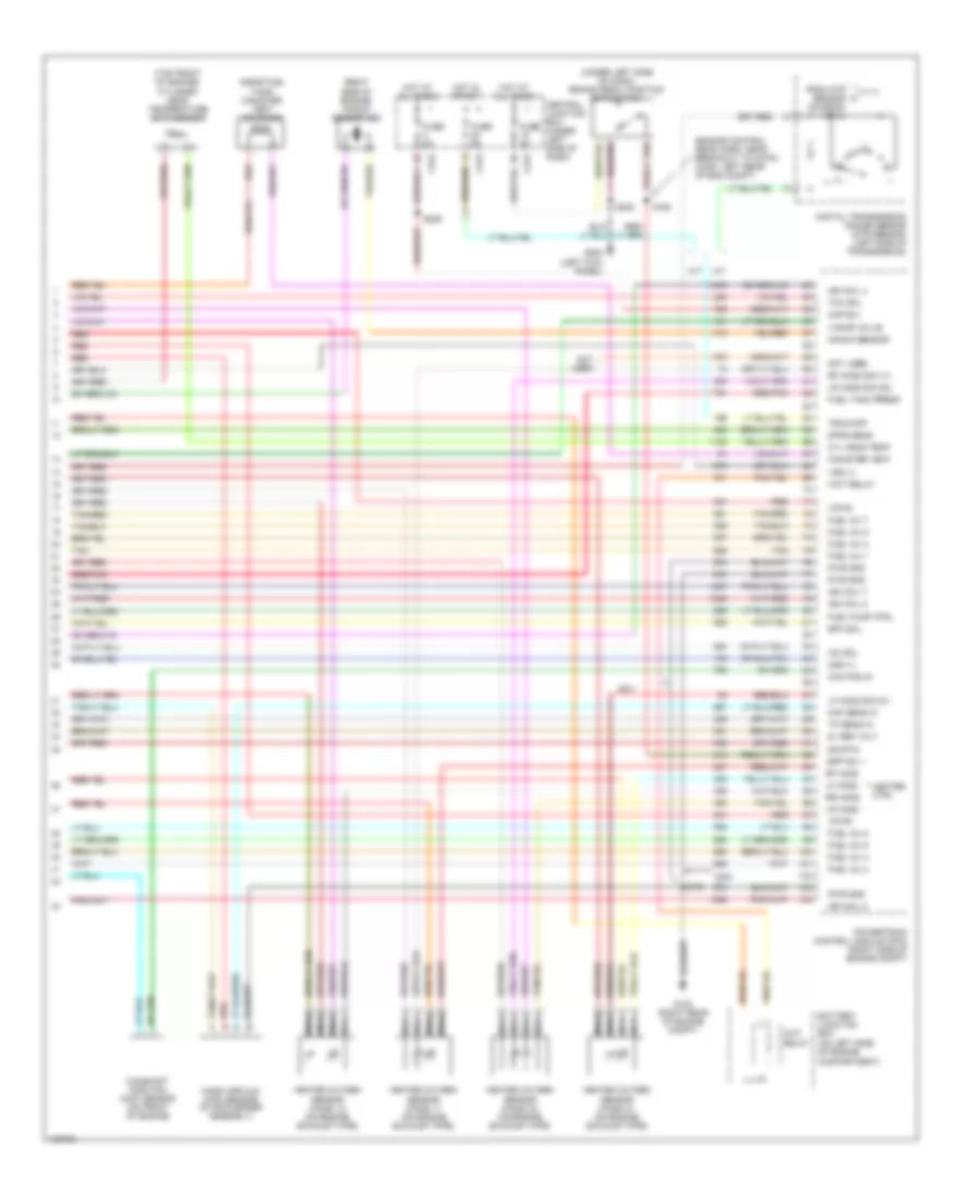
4.2L, Engine Performance Wiring Diagrams (4 of 4) for Ford Pickup F250 Super Duty 2000
List of elements for 4.2L, Engine Performance Wiring Diagrams (4 of 4) for Ford Pickup F250 Super Duty 2000:
- (engine control sensor harn, near breakout to windsheild wiper motor)
- (in left side of engine compt) speed control servo
- (left kick panel)
- (near fuel tank) canister vent solenoid
- (on left side of engine compartment)
- (on left side of engine) cylinder head temperature sensor
- (right side of engine) knock sensor (ks)
- (under left side of dash) brake pedal position (bpp) switch
- 5v ref volt
- A/t
- Battery junction box
- Bpp sw
- C242
- C243
- Cam pos in
- Camshaft position (cmp) sensor (on front of engine)
- Canister vent
- Central junction box (under left side of dash)
- Cyl head temp
- Digital transmission range sensor (left side of transmission)
- Dpfe sens
- Epc sol
- From dtr sensor (diagram 1 of 4)
- Fuel inj 1
- Fuel inj 2
- Fuel inj 3
- Fuel inj 4
- Fuel inj 5
- Fuel inj 6
- Fuel pump ctrl
- Fuel tank press
- Fuse 5a
- G123 (right rear of engine compt)
- G123 (right rear of engine compt)
- G200
- Heated oxygen sensor (ho2s) 11 (on engine exhaust pipe)
- Heated oxygen sensor (ho2s) 12 (on engine exhaust pipe)
- Heated oxygen sensor (ho2s) 21 (on engine exhaust pipe)
- Heated oxygen sensor (ho2s) 22 (on engine exhaust pipe)
- Heater ctrl
- Hot at all times
- Hot in start
- Iac sol
- Ign coil 3
- Kap b(+)
- Knock sensor
- Lf ho2s
- Lf ho2s sig (21)
- Lr ho2s
- Lr ho2s sig (22)
- M/t
- Maf sens in
- Mass airflow (maf) sensor (in air cleaner assembly)
- Nca
- Oss (+)
- Pnk
- Powertrain control module (pcm) (right side of engine compt)
- Pwr gnd
- Red
- Red/pnk
- Ref voltage
- Rf ho2s
- Rf ho2s sig (11)
- Rr ho2s
- S100
- S143
- S208
- S297
- Speed sensor
- Tan
- Tcc sol
- Tp sens in
- Tr3a (a/t) cpp (m/t)
- Trans ctrl ind
- Vapor valve
- Vpwr
- Vss (+)
- Vss input
- Wot relay
4.6L
4.6L, Engine Performance Wiring Diagrams (1 of 4) for Ford Pickup F250 Super Duty 2000
List of elements for 4.6L, Engine Performance Wiring Diagrams (1 of 4) for Ford Pickup F250 Super Duty 2000:
- (4.6l)
- (engine control sensor harn, near breakout to 40-pin connector, left rear left rear corner of eng compt)
- (fuel charge harn, near breakout to 42-pin conn in right rear of engine compt)
- (fuel charge harn, near breakout to fuel injector 3)
- (left front radiator support) g108 (2000/ 2001 supercrew)
- (right rear of engine compt)
- (right rear of fender apron) g105 (2001 except supercrew)
- 4x4 low ind sw
- Accs
- Air conditioning system
- Battery junction box (left side of engine compt)
- Case gnd
- Central junction box (under left side of dash)
- Ckp(+)
- Ckp(-)
- Data link (+)
- Data link (-)
- Data link connector (partial) (under center of dash)
- Digital transmission range sensor (dtr sensor) (left side of transmission)
- Dlc
- Evr ctrl
- Fuel pump mon
- Fuse 30a
- Fuse 5a
- G123
- Hot at all times
- Hot in run or start
- Iat
- Ign coil 1
- Ign coil 3
- Ign coil 5
- Ign coil 6
- Imcc
- Ind
- Instrument cluster system
- Ks sensor
- Maf
- Nca
- Not used
- O/d off
- Pcm power diode
- Pcm power relay
- Pnk
- Powertrain control module (pcm) (right side of engine compt)
- Pwr gnd
- R n
- Radio noise capacitor (left front of engine)
- Radio noise capacitor (right front of engine)
- Rr ho2s sig (12)
- S100
- S106 (or s105)
- S116
- S161
- S162 (fuel charge harn, near breakout to fuel injector 7)
- Shift sol a
- Shift sol b
- Tcil
- Tcs
- Tcss
- Tft
- To dtr sensor (diagram 4 of 4)
- Tr1
- Tr2
- Tr4
- Transmission control switch (a/t)
- Transmission system
4.6L, Engine Performance Wiring Diagrams (2 of 4) for Ford Pickup F250 Super Duty 2000
List of elements for 4.6L, Engine Performance Wiring Diagrams (2 of 4) for Ford Pickup F250 Super Duty 2000:
- (engine control sensor harn, near breakout to 40-pin conn in left rear of engine compt)
- (engine control sensor harn, near breakout to windshield wiper motor)
- (engine control sensor harn, right rear of engine compt)
- Battery junction box (left side of engine compt)
- Crankshaft position (ckp) sensor (lower front of engine)
- Crankshaft position sensor shield
- Differential pressure feedback egr (dpfe) sensor (left side of engine)
- Fuel pump relay
- Fuel tank pressure sensor (in fuel tank)
- Fuse 15a
- Fuse 20a
- G123 (right rear of engine compt)
- Hot at all times
- Intake air temperature (iat) sensor (on intake manifold)
- Intake manifold communicator control (imcc) (4.6l) (right side of engine)
- Nca
- Pnk
- Power distribution box (left side of engine compt)
- Red
- Red/pnk
- S100
- S127
- S135 (fuel charge harn, near breakout to fuel inj 8)
- S136 (fuel charge harn, near breakout to fuel inj 7)
- S137 (engine control sensor harn, near breakout to starter relay)
- S138
- S139
- S199
- Throttle position (tp) sensor (on throttle body)
- Transfer case speed sensor (left rear of trans)
4.6L, Engine Performance Wiring Diagrams (3 of 4) for Ford Pickup F250 Super Duty 2000
List of elements for 4.6L, Engine Performance Wiring Diagrams (3 of 4) for Ford Pickup F250 Super Duty 2000:
- (back-up lamp sw to rear lamp feed harn, in breakout to 38-pin conn in right rear engine compt)
- (engine control sensor harn, near breakout to 40-pin conn, left rear corner
- (engine ctrl sensor harn, near breakout to windsheild wiper motor)
- (fuel charge harn, near breakout to 16-pin conn, right rear of engine compt)
- (fuel charge harn, near breakout to ignition coil 3)
- (fuel tank) fuel pump assembly
- (left side of engine compt) speed control servo
- (under left side of dash) central junction box
- 4r70w transmission
- C267
- Egr vacuum regulator solenoid (left side of engine)
- Electronic pressure control solenoid
- Evap canister purge
- Fuel injectors
- G108 (left front radiator support)
- Generic electronic module
- Idle air control (iac) valve (on left side of intake manifold)
- Inertia fuel shut-off switch (under right side of dash)
- Instrument cluster system
- Nca
- Of engine compt)
- Output shaft speed (oss) sensor (left side of transmission)
- Red
- Red/pnk
- S129
- S131 (fuel charge harn, near breakout to ign coil 7)
- S140
- S141
- S143
- S154
- S155
- S400
- Shift solenoids
- Tan
- Tan/ red
- Tan/red
- Torque converter clutch solenoid
- Transmission fluid temperature sensor
- Valve (left rear corner of engine compt)
- Vss input
4.6L, Engine Performance Wiring Diagrams (4 of 4) for Ford Pickup F250 Super Duty 2000
List of elements for 4.6L, Engine Performance Wiring Diagrams (4 of 4) for Ford Pickup F250 Super Duty 2000:
- (engine control sens harn, near breakout to 40-pin conn, left rear of eng compt)
- (near fuel tank) canister vent solenoid
- (on left side of engine compartment)
- (right side of engine) knock sensor (ks)
- (top front of engine) cylinder head temperature (cht) sensor
- (under left side of dash) brake pedal position (bpp)switch
- 5v ref volt
- A/t
- Battery junction box
- Bpp sw
- Cam pos in
- Camshaft position (cmp) sensor (on front of engine)
- Canister vent
- Central junction box (under left side of dash)
- Cyl head temp
- Digital transmission range sensor (dtr sensor) (left side of transmission)
- Dpfe sens
- Epc sol
- From dtr sensor (diagram 1 of 4)
- Fuel inj 1
- Fuel inj 2
- Fuel inj 3
- Fuel inj 4
- Fuel inj 5
- Fuel inj 6
- Fuel inj 7
- Fuel inj 8
- Fuel pump ctrl
- Fuel tank press
- Fuse 5a
- G123 (right rear of engine compt)
- G200 (left kick panel)
- Heated oxygen sensor (ho2s) 11 (on engine exhaust pipe)
- Heated oxygen sensor (ho2s) 12 (on engine exhaust pipe)
- Heated oxygen sensor (ho2s) 21 (on engine exhaust pipe)
- Heated oxygen sensor (ho2s) 22 (on engine exhaust pipe)
- Heater ctrl
- Hot at all times
- Hot in start
- Iac sol
- Ign coil 2
- Ign coil 4
- Ign coil 7
- Ign coil 8
- Kap b(+)
- Knock sensor
- Lf ho2s
- Lf ho2s sig (21)
- Lr ho2s
- Lr ho2s sig (22)
- M/t
- Maf sens in
- Mass airflow (maf) sensor (in air cleaner assembly)
- Nca
- Not used
- Oss (+)
- Powertrain control module (pcm) (right side of engine compt)
- Pwr gnd
- Red
- Red/pnk
- Rf ho2s
- Rf ho2s sig (11)
- Rr ho2s
- S100
- S160
- S208
- S289
- Sig rtn
- Tan
- Tan/red
- Tcc sol
- Tp sens in
- Tr3a/cpp
- Vapor valve
- Vpwr
- Vss (+)
- Wot relay
5.4L
5.4L Bi-Fuel, Engine Performance Wiring Diagrams (1 of 5) for Ford Pickup F250 Super Duty 2000
List of elements for 5.4L Bi-Fuel, Engine Performance Wiring Diagrams (1 of 5) for Ford Pickup F250 Super Duty 2000:
- (engine control sensor harn, near breakout to 40-pin connector, left rear corner of engine compt)
- (engine control sensor harn, near breakout to starter motor relay)
- (fuel charge harn, near breakout to 42-pin conn in right rear of engine compt)
- (fuel charge harn, near breakout to fuel injector 3)
- (left front radiator support) g108 (2000)
- (rear of right fender apron) g105 (2001)
- (right side of firewall)
- (under left side of dash) generic electronic module
- (vcl/sensor harn, left rear of engine compt)
- 4x4 low & high indicator switch (left side of transmission)
- 4x4 low ind sw
- 4x2
- Accs
- Air conditioning system
- Bare
- Battery junction box (left side of engine compt)
- C239
- C243
- Case gnd
- Center of dash)
- Central junction box (under left side of dash)
- Ckp(+)
- Ckp(-)
- Css
- Data link (+)
- Data link (-)
- Digital transmission range sensor (dtr sensor) (left side of transmission)
- Dlc
- Electronic shift on the fly (esof)
- Evr ctrl
- Fuel pump mon
- Fuse 30a
- Fuse 5a
- G123
- Hot at all times
- Hot in run or start
- Iat
- Ign coil 1
- Ign coil 3
- Ign coil 5
- Ign coil 6
- Imcc
- Ind
- Instrument cluster system
- Ks sensor
- Maf
- Mechanical shift on the fly (msof)
- Nca
- Not used
- O/d off
- Pcm power diode
- Pcm power relay
- Pnk
- Powertrain control module (pcm) (right side of engine compt)
- Pwr gnd
- R n
- Radio noise capacitor (top left side of engine)
- Radio noise capacitor (top right side of engine)
- Rr ho2s sig (12)
- S100
- S106 (or s105)
- S116
- S142
- S161
- S162 (fuel charge harn, near breakout to fuel injector 7)
- S225
- S4003
- S4004
- Shift sol 1
- Shift sol 2
- Tcil
- Tcs
- Tcss
- Tft
- To dtr sensor (diagram 4 of 4)
- Tr1
- Tr2
- Tr4
- Transmission control switch (a/t)
5.4L Bi-Fuel, Engine Performance Wiring Diagrams (2 of 5) for Ford Pickup F250 Super Duty 2000
List of elements for 5.4L Bi-Fuel, Engine Performance Wiring Diagrams (2 of 5) for Ford Pickup F250 Super Duty 2000:
- (cng)
- (engine control sensor harn, near breakout to 40-pin conn in left rear of engine compt)
- (engine control sensor harn, near breakout to windshield wiper motor)
- (engine control sensor harn, right rear of engine compt)
- (fuel charge harn, near breakout to fuel inj 8)
- (lpg)
- (near battery)
- (near fuel tank) front tank valve (cng)
- (near fuel tank) tank valve diode (cng)
- (right rear of body compt) lock off diode
- (right rear of body compt) lock off solenoid
- (right rear of engine compt) cold start heater diode (lpg)
- (under right side of dash) inertia fuel shut-off switch
- Battery junction box (left side of engine compt)
- C236
- Cold start heater (lpg)
- Cold start heater relay (lpg) (right side of engine compt)
- Crankshaft position (ckp) sensor (lower front of engine)
- Differential pressure feedback egr (dpfe) sensor (left side of engine)
- Fuel pump relay
- Fuel reset
- Fuel tank pressure sensor (in fuel tank)
- Fuse 15a
- Fuse 20a
- G123 (right side of firewall)
- Hot at all times
- Instrument cluster
- Intake air temperature (iat) sensor (on intake manifold)
- Nca
- Pnk
- Red
- Red/pnk
- S1003 (engine harn, near breakout to bjb)
- S101
- S127
- S135
- S136 (fuel charge harn, near breakout to fuel inj 7)
- S137 (engine control sensor harn, near breakout to starter relay)
- S138
- S139
- S199
- S4005
- S4006
- S4010
- S4011
- S4012
- S4014 s4031
- S4015
- S4016
- S4020 (vcl/sensor harn, right rear of engine compt)
- S4032
- S4033
- S4034
- S4035
- S4036
- Throttle position (tp) sensor (on throttle body)
- Transfer case speed sensor (left rear of trans)
- Turbine shaft speed (tss) sensor (left rear of trans)
5.4L Bi-Fuel, Engine Performance Wiring Diagrams (3 of 5) for Ford Pickup F250 Super Duty 2000
List of elements for 5.4L Bi-Fuel, Engine Performance Wiring Diagrams (3 of 5) for Ford Pickup F250 Super Duty 2000:
- (b+)
- (compuvalve harn, near fuel tank)
- (compuvalve harn, right rear of engine compt)
- (fuel tank) fuel tank pressure sensor
- (fuel tank) fuel tank temperature sensor
- (right front of engine compt)
- (right front of engine compt) g119
- (vcl/sens harn, right rear of engine compt)
- (vcl/sensor harn, right rear of engine compt)
- 1ooo
- 87a
- Bi-fuel power relay
- Bi-fuel relay module
- Bus (-)
- Ckp (+)
- Ckp (-)
- Cold st
- Compuvalve module
- Cool s
- Coolant solenoid
- F cut
- F send
- F temp
- Fuel pump assembly (fuel tank)
- Fuel pump cutoff relay
- Fuse 3a
- G001
- G002
- G003
- G004
- G005
- G006
- G007
- G008
- G010
- G011
- G013
- G014
- G016
- G017
- G019
- G021
- G022
- G026
- G030
- G032
- G034
- G038
- G045
- G046
- G047
- G049
- G050
- G051
- G052
- G053
- G055
- G057
- G059
- G061
- G062
- G063
- G064
- G119
- G200 (left kick panel)
- Ground
- High flow injector assembly
- Ho2s 11
- Ho2s 21
- Hot at all times
- Ign
- Ind sw
- Indicator light switch
- Inj 1
- Inj 2
- Inj 3
- Inj 4
- Inj 5
- Inj 6
- Inj 7
- Inj 8
- Lk off
- Low flow injector assembly
- Nca
- Not
- Pnk
- Red
- Red/pnk
- Resistor
- S400
- S4001
- S4007
- S4017
- S4021
- Sig rtn
- Tps rtn
5.4L Bi-Fuel, Engine Performance Wiring Diagrams (4 of 5) for Ford Pickup F250 Super Duty 2000
List of elements for 5.4L Bi-Fuel, Engine Performance Wiring Diagrams (4 of 5) for Ford Pickup F250 Super Duty 2000:
- (back-up lamp sw to rear lamp feed harn, in breakout to 38 pin conn, right rear eng compt)
- (back-up lamp sw to rear lamp feed harn, in breakout to 38-pin conn in right rear engine compt)
- (engine control sensor harn, near breakout to 40 pin conn, left rear corner of engine compt)
- (engine ctrl sensor harn, near breakout to windsheild wiper motor)
- (fuel charge harn, near breakout to 16-pin conn, right rear of engine compt)
- (fuel charge harn, near breakout to ignition coil 3)
- (left side of engine compt) speed control servo
- (under left side of dash) central junction box
- 4r100
- 4r70w
- C267
- Coast clutch solenoid (4r100)
- Egr vacuum regulator solenoid (left side of engine)
- Electronic pressure control solenoid
- Evap canister purge valve (left rear corner of eng compt)
- Fuel injectors
- Generic electronic module
- Idle air control (iac) valve (on left side of intake manifold)
- Intake manifold communicator control (imcc) (left side of engine)
- Output shaft speed (oss) sensor (left side of transmission)
- Red
- Red/pnk
- S129
- S131 (fuel charge harn, near breakout to ign coil 7)
- S140
- S141
- S143
- S154
- S155
- Shift solenoid (4r70w)
- Shift solenoid 1 (4r100)
- Shift solenoid 2 (4r100)
- Tan
- Tan/ red
- Tan/red
- Torque converter clutch solenoid
- Transmission
- Transmission fluid temperature sensor
- Vss input
5.4L Bi-Fuel, Engine Performance Wiring Diagrams (5 of 5) for Ford Pickup F250 Super Duty 2000
List of elements for 5.4L Bi-Fuel, Engine Performance Wiring Diagrams (5 of 5) for Ford Pickup F250 Super Duty 2000:
- (engine control sens harn, near breakout to 40-pin conn, left rear of eng compt)
- (near fuel tank) canister vent solenoid
- (on left side of engine compartment)
- (right side of engine) knock sensor (ks)
- (top front of engine) cylinder head temperature (cht) sensor
- (under left side of dash) brake pedal position (bpp) switch
- (vcl/sens harn, right rear of engine compt)
- 5v ref volt
- A/t
- Battery junction box
- Bpp sw
- Cam pos in
- Camshaft position (cmp) sensor (on front of engine)
- Canister vent
- Central junction box (under left side of dash)
- Cyl head temp
- Digital transmission range sensor (dtr sensor) (left side of transmission)
- Dpfe sens
- Epc sol
- From dtr sensor (diagram 1 of 5)
- Fuel inj 1
- Fuel inj 2
- Fuel inj 3
- Fuel inj 4
- Fuel inj 5
- Fuel inj 6
- Fuel inj 7
- Fuel inj 8
- Fuel pump ctrl
- Fuel tank press
- Fuse 5a
- G123 (right side of firewall)
- G200 (left kick panel)
- Heated oxygen sensor (ho2s) 11 (on engine exhaust pipe)
- Heated oxygen sensor (ho2s) 12 (on engine exhaust pipe)
- Heated oxygen sensor (ho2s) 21 (on engine exhaust pipe)
- Heated oxygen sensor (ho2s) 22 (on engine exhaust pipe)
- Heater ctrl
- Hot at all times
- Hot in start
- Iac sol
- Ign coil 2
- Ign coil 4
- Ign coil 7
- Ign coil 8
- Kap b(+)
- Knock sensor
- Lf ho2s
- Lf ho2s sig (21)
- Lr ho2s
- Lr ho2s sig (22)
- M/t
- Maf sens in
- Mass airflow (maf) sensor (in air cleaner assembly)
- Nca
- Oss (+)
- Powertrain control module (pcm) (right side of engine compt)
- Pwr gnd
- Red
- Red/pnk
- Rf ho2s
- Rf ho2s sig (11)
- Rr ho2s
- S100
- S101
- S160
- S199
- S208
- S236
- S4018
- S4019
- Sig rtn
- Tan
- Tan/red
- Tcc sol
- Tp sens in
- Tr3a/cpp
- Tss
- Vapor valve
- Vpwr
- Vss (+)
- Wot relay
5.4L CNG, Engine Performance Wiring Diagrams (1 of 5) for Ford Pickup F250 Super Duty 2000
List of elements for 5.4L CNG, Engine Performance Wiring Diagrams (1 of 5) for Ford Pickup F250 Super Duty 2000:
- (eng ctrl sensor harn, near breakout to 12-pin conn, center front of eng compt)
- (left radiator support) g108 (2000)
- (rear of right fender apron) g105 (2001)
- (under center of dash) (partial) datalink connector
- A/c on sig
- Air conditioning system
- Battery junction box (left side of engine compt)
- Case gnd
- Ccs
- Central junction box (under left side of dash)
- Ckp (+)
- Ckp (-)
- Data link (+)
- Data link (-)
- Digital transmission range sensor (dtr sensor) (left side of transmission)
- Dlc
- Dtr-tr1
- Dtr-tr2
- Dtr-tr4
- Fuel pump mon
- Fuse 30a
- Fuse 5a
- G123 (right rear of engine compt)
- G200 (lower left kick panel)
- Hot at all times
- Hot in run or start
- Iat
- Ign coil 1
- Ign coil 3
- Ign coil 5
- Ign coil 6
- Instrument cluster
- Maf
- Nca
- Ngv timer (left rear of engine compt)
- Not used
- O/d off
- Ohms
- Pcm power diode
- Pcm power relay
- Powertrain control module (right side of engine compt)
- Pwr gnd
- R n
- S116
- S156
- S157
- S207
- S225
- Ss1
- Ss2
- Starting/ charging system
- Tan/red
- Tcil ind
- Tcs
- Tft
- To dtr sensor (diagram 5 of 5)
- Transmission control indicator lamp
- Transmission control switch
5.4L CNG, Engine Performance Wiring Diagrams (2 of 5) for Ford Pickup F250 Super Duty 2000
List of elements for 5.4L CNG, Engine Performance Wiring Diagrams (2 of 5) for Ford Pickup F250 Super Duty 2000:
- (engine control sensor harn, near breakout to 40-pin conn in left rear of engine compt)
- (engine control sensor harn, near breakout to windshield wiper motor)
- (fuel charge harn, near breakout to fuel inj 8)
- (fuel tank harn, near breakout to tank valve 2) s302
- (left side of engine compt) speed control servo
- (under left side of dash) central junction box
- Battery junction box (left side of engine compt)
- C237
- C243
- C267
- Crankshaft position (ckp) sensor (lower front of engine)
- Crankshaft position sensor shield
- Forward in-bed fuel tank valve (at fuel tank)
- Fuel gauge
- Fuse 15a
- G108 (left front radiator support)
- G123 (right rear of engine compt)
- Generic electronic module/ central timer module
- Inertia fuel shut-off switch (under right side of dash)
- Injection pressure sensor (ips) (on top of engine)
- Instrument cluster
- Intake air temperature (iat) sensor (on intake manifold)
- Midship fuel tank valve (at fuel tank)
- Nca
- Rear in-bed fuel tank valve (at fuel tank)
- Red
- Red/pnk
- S101
- S135
- S136 (fuel charge harn, near breakout to ing coil 4)
- S139
- S143
- S159 (engine ctrl sensor harn, near breakout to wiper motor)
- S199
- S301
- Throttle position (tp) sensor (on throttle body)
- Vss input
5.4L CNG, Engine Performance Wiring Diagrams (3 of 5) for Ford Pickup F250 Super Duty 2000
List of elements for 5.4L CNG, Engine Performance Wiring Diagrams (3 of 5) for Ford Pickup F250 Super Duty 2000:
- (back-up lamp harn, at breakout to 38-pin conn in right rear of engine compt)
- Battery junction box (left side of engine compt)
- Coast clutch solenoid
- Electronic pressure control solenoid
- Fuel rail cutoff valve (on fuel rail)
- Fuel shutoff valve relay
- Fuse 20a
- G117 (lower right rear of engine)
- Hot at all times
- Ignition coils
- Nca
- R4100 transmission
- Radio noise capacitor (on top left side of engine)
- Radio noise capacitor (on top right side of engine)
- Red
- Red red
- Red/pnk
- S117 (fuel charge harn, near breakout to 42-pin inline conn in right rear of engine compt)
- S140
- S153
- S161 (fuel charge harn, in breakout to injector 3)
- S162 (fuel charge harn, in breakout to injector 7)
- Shift solenoid
- Torque converter clutch solenoid
- Transmission fluid temperature sensor
5.4L CNG, Engine Performance Wiring Diagrams (4 of 5) for Ford Pickup F250 Super Duty 2000
List of elements for 5.4L CNG, Engine Performance Wiring Diagrams (4 of 5) for Ford Pickup F250 Super Duty 2000:
- (eng control sens harn, near breakout to wiper motor)
- Data (+)
- Data (-)
- Fuel gauge
- Fuel injectors
- Fuel press
- Fuel temp
- Ground
- Ignition
- Inj 1 input
- Inj 1 out
- Inj 2 input
- Inj 2 out
- Inj 3 input
- Inj 3 out
- Inj 4 input
- Inj 4 out
- Inj 5 input
- Inj 5 out
- Inj 6 input
- Inj 6 out
- Inj 7 input
- Inj 7 out
- Inj 8 input
- Inj 8 out
- Ngv fuel tank pressure sensor (at fuel tank)
- Ngv fuel tank temperature sensor (at fuel tank)
- Ngv module (on front of engine)
- Output shaft speed (oss) sensor (on left side of transmission)
- Power
- Red
- Red/pnk
- S127
- S129 (fuel charge harn, near breakout to ign coil 3)
- S131 (fuel charge harn, near breakout ign coil 7)
- S303 (fuel tank harn, near fuel tank)
- Sig return
- Tan
- Tan/ red
- Tan/red
- Timer
5.4L CNG, Engine Performance Wiring Diagrams (5 of 5) for Ford Pickup F250 Super Duty 2000
List of elements for 5.4L CNG, Engine Performance Wiring Diagrams (5 of 5) for Ford Pickup F250 Super Duty 2000:
- (back-up lamp harn, in breakout to 38-pin conn in right rear eng compt)
- (eng cntrl sens harn)
- (engine control sensor harn, right rear of engine compt)
- (fuel charge harness)
- (left rear of trans) turbine shaft speed sensor
- (left side of dash) brake pedal position (bpp) switch
- (main harn, near breakout to instrument cluster)
- (top front of left head) cylinder head temperature sensor
- 270 ohms
- 5v ref
- Battery junctioin box (in left side of engine compt)
- Bpp switch
- C242
- C243
- Camshaft position (cmp) sensor (on front of engine)
- Central junction box (under left side of dash)
- Cmp sensor
- Cyl head temp
- Digital transmission range sensor (dtr sensor-a/t) (left side of transmission)
- Dtr-tr3a
- Eft sensor
- Engine fuel temperature (eft-a) sensor (on top of engine)
- Epc sol
- From dtr sensor (diagram 1 of 5)
- Fuel ctrl
- Fuse 5a
- G123 (right rear of engine compt)
- G200 (lower left kick panel)
- Heated oxygen sensor (ho2s) 11 (on engine exhaust pipe)
- Heated oxygen sensor (ho2s) 21 (on engine exhaust pipe)
- Ho2s (11)
- Ho2s (21)
- Ho2s sig (#11)
- Ho2s sig (21)
- Hot at all times
- Idle air control valve (on left side of intake manifold)
- Idle air ctrl
- Ign coil 2
- Ign coil 4
- Ign coil 7
- Ign coil 8
- Inj pressure
- Kap b(+)
- Maf sens in
- Mass airflow (maf) sensor (in air cleaner assembly)
- Nca
- Ngv module
- Not used
- Oss sensor
- Powertrain control module (right side of engine compt)
- Pwr gnd
- Red
- Red/pnk
- S100
- S138
- S141
- S154
- S155
- S158
- Sig rtn
- Tcc sol
- Tp sens in
- Tss sensor
- Vpwr
- Vss (+)
- Wire terminates in harness
- Wot relay
5.4L Supercharged, Engine Performance Wiring Diagrams (1 of 4) for Ford Pickup F250 Super Duty 2000
List of elements for 5.4L Supercharged, Engine Performance Wiring Diagrams (1 of 4) for Ford Pickup F250 Super Duty 2000:
- (engine control sensor harn, near breakout to 40-pin connector, left rear left rear corner of eng compt)
- (fuel charge harn, near breakout to 42-pin conn in right rear of engine compt)
- (fuel charge harn, near breakout to fuel injector 3)
- (right rear of engine compt)
- A/c system
- Accs
- Battery junction box (left side of engine compt)
- C243
- Case gnd
- Central junction box (under left side of dash)
- Ckp(+)
- Ckp(-)
- Css
- Data link (+)
- Data link (-)
- Data link connector (partial) (under center of dash)
- Digital transmission range sensor (dtr sensor) (left side of transmission)
- Dlc
- Evr ctrl
- Fuel h/l rly
- Fuel pump mon
- Fuse 15a
- Fuse 30a
- Fuse 5a
- G108 (left front radiator support)
- G123
- Hot at all times
- Hot in run or start
- Iat
- Ign coil 1
- Ign coil 3
- Ign coil 5
- Ign coil 6
- Ind
- Instrument cluster system
- Ks sensor
- Maf
- Nca
- Not used
- O/d off
- Pcm power diode
- Pcm power relay
- Powertrain control module (pcm) (right side of engine compt)
- Pwr gnd
- R n
- Radio noise capacitor (top left side of engine)
- Radio noise capacitor (top right side of engine)
- Red
- Rr ho2s sig (12)
- S100
- S1003 (engine control sensor harn, near breakout to battery junction box)
- S106
- S116
- S161
- S162 (fuel charge harn, near breakout to fuel injector 7)
- S225
- Shift sol a
- Shift sol b
- Tcil
- Tcs
- Tft
- To dtr sensor (diagram 4 of 4)
- Tr1
- Tr2
- Tr4
- Transmission control switch (a/t)
5.4L Supercharged, Engine Performance Wiring Diagrams (2 of 4) for Ford Pickup F250 Super Duty 2000
List of elements for 5.4L Supercharged, Engine Performance Wiring Diagrams (2 of 4) for Ford Pickup F250 Super Duty 2000:
- (engine control harn, left front corner of vehicle)
- (engine control harn, left front corner of vehicle) s151
- (engine control sensor harn, right rear of engine compt)
- (left front radiator support)
- (left front radiator support) g108
- (rear of right fender apron) g105
- 87a
- Battery junction box (left side of engine compt)
- Charge air cooler pump motor (left front of engine compt)
- Charge air cooler pump relay
- Crankshaft position (ckp) sensor (lower front of engine)
- Crankshaft position sensor shield
- Differential pressure feedback egr (dpfe) sensor (left side of engine)
- Fuel pump assembly (at fuel tank)
- Fuel pump dropping resistor (left front of engine compt)
- Fuel pump high/low relay
- Fuel pump relay
- Fuel tank pressure sensor (in fuel tank)
- Fuse 20a
- G108
- G108 (left front radiator support)
- G123 (right rear of engine compt)
- Hot at all times
- Inertia fuel shut-off switch (under right side of dash)
- Inertia switch relay
- Instrument cluster system
- Intake air temperature (iat) sensor (on intake manifold)
- Nca
- Red
- Red/pnk
- S100
- S102
- S106
- S127 (engine control sensor harn, near breakout to windshield wiper motor)
- S135 (fuel charge harn, near breakout to fuel inj 8)
- S136 (fuel charge harn, near breakout to fuel inj 7)
- S137 (engine control sensor harn, near breakout to starter relay)
- S138
- S144
- S199
- Throttle position (tp) sensor (on throttle body)
- Turbine shaft speed (tss) sensor (left rear of trans)
5.4L Supercharged, Engine Performance Wiring Diagrams (3 of 4) for Ford Pickup F250 Super Duty 2000
List of elements for 5.4L Supercharged, Engine Performance Wiring Diagrams (3 of 4) for Ford Pickup F250 Super Duty 2000:
- (back-up lamp sw to rear lamp feed harn, in breakout to 38-pin conn in right rear engine compt)
- (engine control sensor harn, near breakout to 40-pin conn, left rear corner of engine compt)
- (engine ctrl sensor harn, near breakout to windsheild wiper motor)
- (fuel charge harn, near breakout to 16-pin conn, right rear of engine compt)
- (fuel charge harn, near breakout to ignition coil 3)
- (left side of engine compt) speed control servo
- (under left side of dash) central junction box
- 4r100 transmission
- C267
- Coast clutch solenoid
- Egr vacuum regulator solenoid (left side of engine)
- Electronic pressure control solenoid
- Evap canister purge
- Fuel injectors
- Generic electronic module
- Idle air control (iac) valve (on left side of intake manifold)
- Output shaft speed (oss) sensor (left side of transmission)
- Red
- Red/pnk
- S129
- S131 (fuel charge harn, near breakout to ign coil 7)
- S140
- S141
- S143
- S154
- S155
- Shift solenoid
- Tan
- Tan/ red
- Tan/red
- Torque converter clutch solenoid
- Transmission fluid temperature sensor
- Valve (left rear corner of engine compt)
- Vss input
5.4L Supercharged, Engine Performance Wiring Diagrams (4 of 4) for Ford Pickup F250 Super Duty 2000
List of elements for 5.4L Supercharged, Engine Performance Wiring Diagrams (4 of 4) for Ford Pickup F250 Super Duty 2000:
- (engine control sens harn, near breakout to 40-pin conn, left rear of eng compt)
- (near fuel tank) canister vent solenoid
- (on left side of engine compartment)
- (right side of engine) knock sensor (ks)
- (top front of engine) cylinder head temperature (cht) sensor
- (under left side of dash) brake pedal position (bpp) switch
- 5v ref volt
- A/t
- Air cool rly
- Battery junction box
- Bpp sw
- Cam pos in
- Camshaft position (cmp) sensor (on front of engine)
- Camshaft position sensor shield
- Canister vent
- Central junction box (under left side of dash)
- Cyl head temp
- Digital transmission range sensor (dtr sensor) (left side of transmission)
- Dpfe sens
- Epc sol
- From dtr sensor (diagram 1 of 4)
- Fuel inj 1
- Fuel inj 2
- Fuel inj 3
- Fuel inj 4
- Fuel inj 5
- Fuel inj 6
- Fuel inj 7
- Fuel inj 8
- Fuel pump ctrl
- Fuel tank press
- Fuse 5a
- G123 (right rear of engine compt)
- G200 (left kick panel)
- Heated oxygen sensor (ho2s) 11 (on engine exhaust pipe)
- Heated oxygen sensor (ho2s) 12 (on engine exhaust pipe)
- Heated oxygen sensor (ho2s) 21 (on engine exhaust pipe)
- Heated oxygen sensor (ho2s) 22 (on engine exhaust pipe)
- Heater ctrl
- Hot at all times
- Hot in start
- Iac sol
- Ign coil 2
- Ign coil 4
- Ign coil 7
- Ign coil 8
- Kap b(+)
- Knock sensor
- Lf ho2s
- Lf ho2s sig (21)
- Lr ho2s
- Lr ho2s sig (22)
- M/t
- Maf sens in
- Mass airflow (maf) sensor (in air cleaner assembly)
- Nca
- Not used
- Oss (+)
- Powertrain control module (pcm) (right side of engine compt)
- Pwr gnd
- Red
- Red/pnk
- Rf ho2s
- Rf ho2s sig (11)
- Rr ho2s
- S100
- S160
- S208
- S289
- Sig rtn
- Tan
- Tan/red
- Tcc sol
- Tp sens in
- Tr3a/cpp
- Tss
- Vapor valve
- Vpwr
- Vss (+)
- Wot relay
5.4L, Engine Performance Wiring Diagrams, with 4R100 Transmission (1 of 4) for Ford Pickup F250 Super Duty 2000
List of elements for 5.4L, Engine Performance Wiring Diagrams, with 4R100 Transmission (1 of 4) for Ford Pickup F250 Super Duty 2000:
- (engine control sensor harn, near breakout to 40-pin connector, left rear left rear corner of eng compt)
- (fuel charge harn, near breakout to 42-pin conn in right rear of engine compt)
- (fuel charge harn, near breakout to fuel injector 3)
- (left front radiator support) g108 (2000/ 2001 supercrew)
- (rear of right fender apron) g105 (2001 except supercrew)
- (right rear of engine compt)
- 4x4 low ind sw
- Accs
- Air conditioning system
- Battery junction box (left side of engine compt)
- C243
- Case gnd
- Central junction box (under left side of dash)
- Ckp(+)
- Ckp(-)
- Css
- Data link (+)
- Data link (-)
- Data link connector (partial) (under center of dash)
- Digital transmission range sensor (dtr sensor) (left side of transmission)
- Dlc
- Evr ctrl
- Fuel pump mon
- Fuse 30a
- Fuse 5a
- G123
- Hot at all times
- Hot in run or start
- Iat
- Ign coil 1
- Ign coil 3
- Ign coil 5
- Ign coil 6
- Ind
- Instrument cluster system
- Ks sensor
- Maf
- Nca
- Not used
- O/d off
- Pcm power diode
- Pcm power relay
- Pnk
- Powertrain control module (pcm) (right side of engine compt)
- Pwr gnd
- R n
- Radio noise capacitor (top left side of engine)
- Radio noise capacitor (top right side of engine)
- Rr ho2s sig (12)
- S100
- S106 (or s105)
- S116
- S161
- S162 (fuel charge harn, near breakout to fuel injector 7)
- S225
- Shift sol a
- Shift sol b
- Tcil
- Tcs
- Tcss
- Tft
- To dtr sensor (diagram 4 of 4)
- Tr1
- Tr2
- Tr4
- Transmission control switch (a/t)
- Transmission system
5.4L, Engine Performance Wiring Diagrams, with 4R100 Transmission (2 of 4) for Ford Pickup F250 Super Duty 2000
List of elements for 5.4L, Engine Performance Wiring Diagrams, with 4R100 Transmission (2 of 4) for Ford Pickup F250 Super Duty 2000:
- (engine control sensor harn, near breakout to 40-pin conn in left rear of engine compt)
- (engine control sensor harn, near breakout to windshield wiper motor) s127
- (engine control sensor harn, right rear of engine compt)
- (fuel tank) fuel pump assembly
- (under right side of dash) inertia fuel shut-off switch
- Battery junction box (left side of engine compt)
- Crankshaft position (ckp) sensor (lower front of engine)
- Crankshaft position sensor shield
- Differential pressure feedback egr (dpfe) sensor (left side of engine)
- Fuel pump relay
- Fuel tank pressure sensor (in fuel tank)
- Fuse 15a
- Fuse 20a
- G108 (left front radiator support)
- G123 (right rear of engine compt)
- Hot at all times
- Instrument cluster system
- Intake air temperature (iat) sensor (on intake manifold)
- Nca
- Pnk
- Power distribution box (left side of engine compt)
- Red
- Red/pnk
- S100
- S135 (fuel charge harn, near breakout to fuel inj 8)
- S136 (fuel charge harn, near breakout to fuel inj 7)
- S137 (engine control sensor harn, near breakout to starter relay)
- S138
- S139
- S199
- S400
- Throttle position (tp) sensor (on throttle body)
- Transfer case speed sensor (left rear of trans)
- Turbine shaft speed (tss) sensor (left rear of trans)
5.4L, Engine Performance Wiring Diagrams, with 4R100 Transmission (3 of 4) for Ford Pickup F250 Super Duty 2000
List of elements for 5.4L, Engine Performance Wiring Diagrams, with 4R100 Transmission (3 of 4) for Ford Pickup F250 Super Duty 2000:
- (back-up lamp sw to rear lamp feed harn, in breakout to 38-pin conn in right rear engine compt)
- (engine control sensor harn, near breakout to 40-pin conn, left rear corner of engine compt)
- (engine ctrl sensor harn, near breakout to windsheild wiper motor)
- (fuel charge harn, near breakout to 16-pin conn, right rear of engine compt)
- (fuel charge harn, near breakout to ignition coil 3)
- (left side of engine compt) speed control servo
- (under left side of dash) central junction box
- 4r100 transmission
- C267
- Coast clutch solenoid
- Egr vacuum regulator solenoid (left side of engine)
- Electronic pressure control solenoid
- Evap canister purge
- Fuel injectors
- Generic electronic module
- Idle air control (iac) valve (on left side of intake manifold)
- Output shaft speed (oss) sensor (left side of transmission)
- Red
- Red/pnk
- S129
- S131 (fuel charge harn, near breakout to ign coil 7)
- S140
- S141
- S143
- S154
- S155
- Shift solenoid
- Tan
- Tan/ red
- Tan/red
- Torque converter clutch solenoid
- Transmission fluid temperature sensor
- Valve (left rear corner of engine compt)
- Vss input
5.4L, Engine Performance Wiring Diagrams, with 4R100 Transmission (4 of 4) for Ford Pickup F250 Super Duty 2000
List of elements for 5.4L, Engine Performance Wiring Diagrams, with 4R100 Transmission (4 of 4) for Ford Pickup F250 Super Duty 2000:
- (engine control sens harn, near breakout to 40-pin conn, left rear of eng compt)
- (near fuel tank) canister vent solenoid
- (on left side of engine compartment)
- (right side of engine) knock sensor (ks)
- (top front of engine) cylinder head temperature (cht) sensor
- (under left side of dash) brake pedal position (bpp) switch
- 5v ref volt
- A/t
- Battery junction box
- Bpp sw
- Cam pos in
- Camshaft position (cmp) sensor (on front of engine)
- Canister vent
- Central junction box (under left side of dash)
- Cyl head temp
- Digital transmission range sensor (dtr sensor) (left side of transmission)
- Dpfe sens
- Epc sol
- From dtr sensor (diagram 1 of 4)
- Fuel inj 1
- Fuel inj 2
- Fuel inj 3
- Fuel inj 4
- Fuel inj 5
- Fuel inj 6
- Fuel inj 7
- Fuel inj 8
- Fuel pump ctrl
- Fuel tank press
- Fuse 5a
- G123 (right rear of engine compt)
- G200 (left kick panel)
- Heated oxygen sensor (ho2s) 11 (on engine exhaust pipe)
- Heated oxygen sensor (ho2s) 12 (on engine exhaust pipe)
- Heated oxygen sensor (ho2s) 21 (on engine exhaust pipe)
- Heated oxygen sensor (ho2s) 22 (on engine exhaust pipe)
- Heater ctrl
- Hot at all times
- Hot in start
- Iac sol
- Ign coil 2
- Ign coil 4
- Ign coil 7
- Ign coil 8
- Kap b(+)
- Knock sensor
- Lf ho2s
- Lf ho2s sig (21)
- Lr ho2s
- Lr ho2s sig (22)
- M/t
- Maf sens in
- Mass airflow (maf) sensor (in air cleaner assembly)
- Nca
- Oss (+)
- Powertrain control module (pcm) (right side of engine compt)
- Pwr gnd
- Red
- Red/pnk
- Rf ho2s
- Rf ho2s sig (11)
- Rr ho2s
- S100
- S160
- S208
- S289
- Sig rtn
- Tan
- Tan/red
- Tcc sol
- Tp sens in
- Tr3a/cpp
- Tss
- Vapor valve
- Vpwr
- Vss (+)
- Wot relay
5.4L, Engine Performance Wiring Diagrams, with 4R70W Transmission (1 of 4) for Ford Pickup F250 Super Duty 2000
List of elements for 5.4L, Engine Performance Wiring Diagrams, with 4R70W Transmission (1 of 4) for Ford Pickup F250 Super Duty 2000:
- (4.6l)
- (engine control sensor harn, near breakout to 40-pin connector, left rear left rear corner of eng compt)
- (fuel charge harn, near breakout to 42-pin conn in right rear of engine compt)
- (fuel charge harn, near breakout to fuel injector 3)
- (left front radiator support) g108 (2000/ 2001 supercrew)
- (right rear of engine compt)
- (right rear of fender apron) g105 (2001 except supercrew)
- 4x4 low ind sw
- Accs
- Air conditioning system
- Battery junction box (left side of engine compt)
- Case gnd
- Central junction box (under left side of dash)
- Ckp(+)
- Ckp(-)
- Data link (+)
- Data link (-)
- Data link connector (partial) (under center of dash)
- Digital transmission range sensor (dtr sensor) (left side of transmission)
- Dlc
- Evr ctrl
- Fuel pump mon
- Fuse 30a
- Fuse 5a
- G123
- Hot at all times
- Hot in run or start
- Iat
- Ign coil 1
- Ign coil 3
- Ign coil 5
- Ign coil 6
- Imcc
- Ind
- Instrument cluster system
- Ks sensor
- Maf
- Nca
- Not used
- O/d off
- Pcm power diode
- Pcm power relay
- Pnk
- Powertrain control module (pcm) (right side of engine compt)
- Pwr gnd
- R n
- Radio noise capacitor (left front of engine)
- Radio noise capacitor (right front of engine)
- Rr ho2s sig (12)
- S100
- S106 (or s105)
- S116
- S161
- S162 (fuel charge harn, near breakout to fuel injector 7)
- Shift sol a
- Shift sol b
- Tcil
- Tcs
- Tcss
- Tft
- To dtr sensor (diagram 4 of 4)
- Tr1
- Tr2
- Tr4
- Transmission control switch (a/t)
- Transmission system
5.4L, Engine Performance Wiring Diagrams, with 4R70W Transmission (2 of 4) for Ford Pickup F250 Super Duty 2000
List of elements for 5.4L, Engine Performance Wiring Diagrams, with 4R70W Transmission (2 of 4) for Ford Pickup F250 Super Duty 2000:
- (engine control sensor harn, near breakout to 40-pin conn in left rear of engine compt)
- (engine control sensor harn, near breakout to windshield wiper motor)
- (engine control sensor harn, right rear of engine compt)
- Battery junction box (left side of engine compt)
- Crankshaft position (ckp) sensor (lower front of engine)
- Crankshaft position sensor shield
- Differential pressure feedback egr (dpfe) sensor (left side of engine)
- Fuel pump relay
- Fuel tank pressure sensor (in fuel tank)
- Fuse 15a
- Fuse 20a
- G123 (right rear of engine compt)
- Hot at all times
- Intake air temperature (iat) sensor (on intake manifold)
- Intake manifold communicator control (imcc) (4.6l) (right side of engine)
- Nca
- Pnk
- Power distribution box (left side of engine compt)
- Red
- Red/pnk
- S100
- S127
- S135 (fuel charge harn, near breakout to fuel inj 8)
- S136 (fuel charge harn, near breakout to fuel inj 7)
- S137 (engine control sensor harn, near breakout to starter relay)
- S138
- S139
- S199
- Throttle position (tp) sensor (on throttle body)
- Transfer case speed sensor (left rear of trans)
5.4L, Engine Performance Wiring Diagrams, with 4R70W Transmission (3 of 4) for Ford Pickup F250 Super Duty 2000
List of elements for 5.4L, Engine Performance Wiring Diagrams, with 4R70W Transmission (3 of 4) for Ford Pickup F250 Super Duty 2000:
- (back-up lamp sw to rear lamp feed harn, in breakout to 38-pin conn in right rear engine compt)
- (engine control sensor harn, near breakout to 40-pin conn, left rear corner
- (engine ctrl sensor harn, near breakout to windsheild wiper motor)
- (fuel charge harn, near breakout to 16-pin conn, right rear of engine compt)
- (fuel charge harn, near breakout to ignition coil 3)
- (fuel tank) fuel pump assembly
- (left side of engine compt) speed control servo
- (under left side of dash) central junction box
- 4r70w transmission
- C267
- Egr vacuum regulator solenoid (left side of engine)
- Electronic pressure control solenoid
- Evap canister purge
- Fuel injectors
- G108 (left front radiator support)
- Generic electronic module
- Idle air control (iac) valve (on left side of intake manifold)
- Inertia fuel shut-off switch (under right side of dash)
- Instrument cluster system
- Nca
- Of engine compt)
- Output shaft speed (oss) sensor (left side of transmission)
- Red
- Red/pnk
- S129
- S131 (fuel charge harn, near breakout to ign coil 7)
- S140
- S141
- S143
- S154
- S155
- S400
- Shift solenoids
- Tan
- Tan/ red
- Tan/red
- Torque converter clutch solenoid
- Transmission fluid temperature sensor
- Valve (left rear corner of engine compt)
- Vss input
5.4L, Engine Performance Wiring Diagrams, with 4R70W Transmission (4 of 4) for Ford Pickup F250 Super Duty 2000
List of elements for 5.4L, Engine Performance Wiring Diagrams, with 4R70W Transmission (4 of 4) for Ford Pickup F250 Super Duty 2000:
- (engine control sens harn, near breakout to 40-pin conn, left rear of eng compt)
- (near fuel tank) canister vent solenoid
- (on left side of engine compartment)
- (right side of engine) knock sensor (ks)
- (top front of engine) cylinder head temperature (cht) sensor
- (under left side of dash) brake pedal position (bpp)switch
- 5v ref volt
- A/t
- Battery junction box
- Bpp sw
- Cam pos in
- Camshaft position (cmp) sensor (on front of engine)
- Canister vent
- Central junction box (under left side of dash)
- Cyl head temp
- Digital transmission range sensor (dtr sensor) (left side of transmission)
- Dpfe sens
- Epc sol
- From dtr sensor (diagram 1 of 4)
- Fuel inj 1
- Fuel inj 2
- Fuel inj 3
- Fuel inj 4
- Fuel inj 5
- Fuel inj 6
- Fuel inj 7
- Fuel inj 8
- Fuel pump ctrl
- Fuel tank press
- Fuse 5a
- G123 (right rear of engine compt)
- G200 (left kick panel)
- Heated oxygen sensor (ho2s) 11 (on engine exhaust pipe)
- Heated oxygen sensor (ho2s) 12 (on engine exhaust pipe)
- Heated oxygen sensor (ho2s) 21 (on engine exhaust pipe)
- Heated oxygen sensor (ho2s) 22 (on engine exhaust pipe)
- Heater ctrl
- Hot at all times
- Hot in start
- Iac sol
- Ign coil 2
- Ign coil 4
- Ign coil 7
- Ign coil 8
- Kap b(+)
- Knock sensor
- Lf ho2s
- Lf ho2s sig (21)
- Lr ho2s
- Lr ho2s sig (22)
- M/t
- Maf sens in
- Mass airflow (maf) sensor (in air cleaner assembly)
- Nca
- Not used
- Oss (+)
- Powertrain control module (pcm) (right side of engine compt)
- Pwr gnd
- Red
- Red/pnk
- Rf ho2s
- Rf ho2s sig (11)
- Rr ho2s
- S100
- S160
- S208
- S289
- Sig rtn
- Tan
- Tan/red
- Tcc sol
- Tp sens in
- Tr3a/cpp
- Vapor valve
- Vpwr
- Vss (+)
- Wot relay