
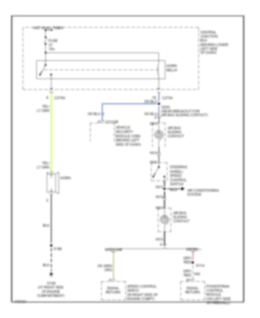
HORN
Horn Wiring Diagram for Ford F450 Super Duty 2003
List of elements for Horn Wiring Diagram for Ford F450 Super Duty 2003:
AIR CONDITIONINGCOMPUTER DATA LINESANTI-LOCK BRAKESELECTRONIC SUSPENSIONCRUISE CONTROLCOOLING FANANTI-THEFTHEADLIGHTSENGINE PERFORMANCEINTERIOR LIGHTSGROUND DISTRIBUTIONEXTERIOR LIGHTSHORNINSTRUMENT CLUSTERPOWER DISTRIBUTIONPOWER DOOR LOCKSPOWER MIRRORSPOWER WINDOWSSTARTING/CHARGINGRADIOWARNING SYSTEMSPOWER SEATSSUPPLEMENTAL RESTRAINTSTRANSMISSIONSHIFT INTERLOCKWIPER/WASHER