POWER DISTRIBUTION
Power Distribution Wiring Diagram (1 of 2) for Oldsmobile Alero GX 2003

List of elements for Power Distribution Wiring Diagram (1 of 2) for Oldsmobile Alero GX 2003:
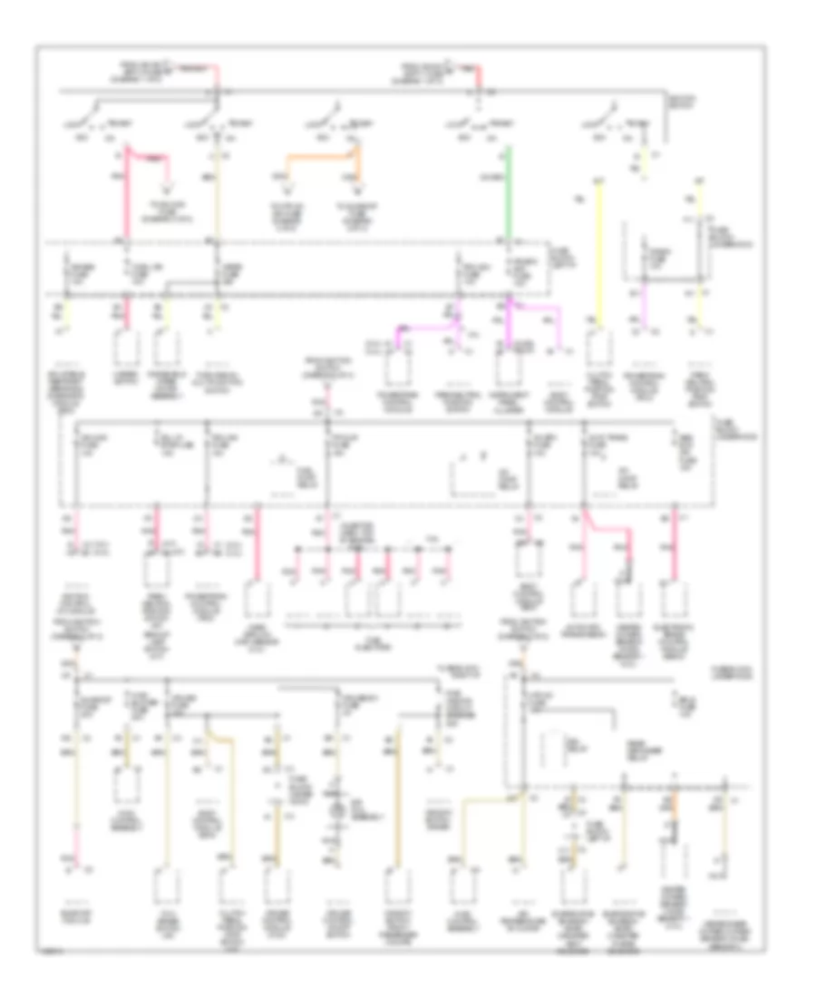
Power Distribution Wiring Diagram (2 of 2) for Oldsmobile Alero GX 2003
List of elements for Power Distribution Wiring Diagram (2 of 2) for Oldsmobile Alero GX 2003: