STARTING/CHARGING
Charging Wiring Diagram for Ford Aspire 1997

List of elements for Charging Wiring Diagram for Ford Aspire 1997:
- (top left front of engine) g110
- Battery
- C209
- C210
- Charge indicator
- Dash fuse box (left side of i/p)
- Engine compartment fuse box (left side of engine compartment)
- Generator/ voltage regulator (right front of engine)
- Head fuse 30a
- Hot in start or run
- Instrument cluster
- Main fuse 80a
- Meter fuse 15a
- Red
- S112
- S114
- S202
- Starter motor/ solenoid (lower right front of engine)
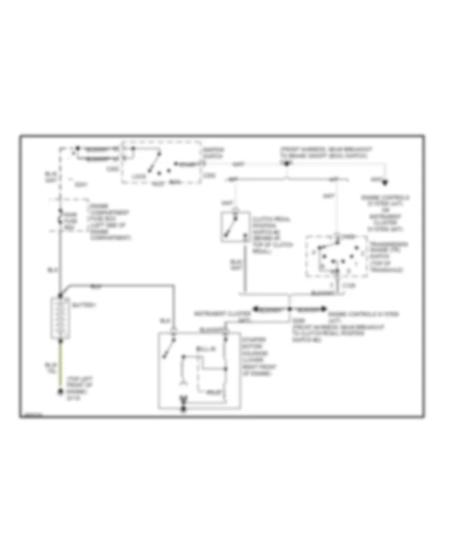
Starting Wiring Diagram for Ford Aspire 1997
List of elements for Starting Wiring Diagram for Ford Aspire 1997:
- (front harness, near breakout to brake on/off (boo) switch) s205
- (top left front of engine) g110
- A/t
- Acc
- Battery
- C129
- C202
- Clutch pedal position switch #2 (behind i/p, top of clutch pedal)
- Engine compartment fuse box (left side of engine compartment)
- Engine controls system (a/t)
- Engine controls system (a/t) or instrument cluster system (m/t)
- Hold
- Ignition switch
- Instrument cluster (m/t)
- Lock
- M/t
- Main fuse 80a
- Pull-in
- Run
- S206 (front harness, near breakout to clutch pedal position switch #2)
- S241
- Start
- Starter motor/ solenoid (lower right front of engine)
- Transmission range (tr) switch (top of transaxle)
 English