ANTI-LOCK BRAKES
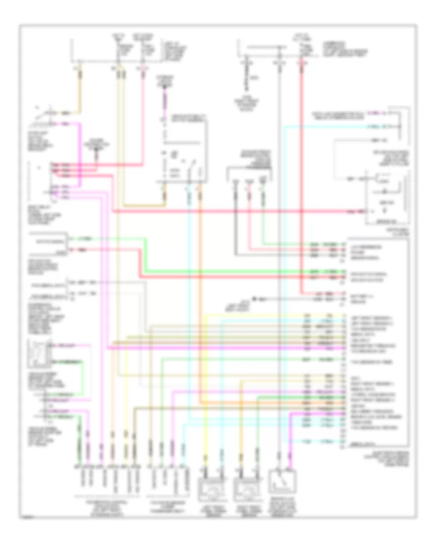
Anti-lock Brake Wiring Diagrams, with Traction Control for GMC Yukon Denali 2002

List of elements for Anti-lock Brake Wiring Diagrams, with Traction Control for GMC Yukon Denali 2002:
- A4 c1
- Abs fuse 60a
- Abs ind
- Body relay block (under left side of dash, near kick panel)
- Brake fluid level sw in
- Brake fluid level switch (on left side of brake fluid reservoir)
- Brake fuse 10a
- Brake in
- Brake ind
- Brake input
- C8 a
- Data link connector (dlc) (below steering column)
- Del torque
- Delivered torque
- Electronic brake control module (ebcm) (on left side of inner frame)
- F6 c3
- F7 c2
- G105 (right front of engine block)
- G110 (left front body mount)
- G203 (upper left side of dash, at "a" pillar)
- Ground
- Ground distribution system
- Hot at all times
- Hot in run
- Hot in run or start
- Ign 1 fuse 10a
- Ignition
- Illum lamp
- Instrument cluster
- Interior lights system
- Left front sensor (+)
- Left front sensor (-)
- Left front wheel speed sensor
- Left i/p fuse block (on lower left side of dash)
- Logic
- Low traction indicator
- Motor & solenoid pwr
- Nca
- Pnk
- Power distribution system
- Powertrain control module (pcm) (on left front of engine compt)
- Red
- Req torque
- Requested torque
- Right front sensor (+)
- Right front sensor (-)
- Right front wheel speed sensor
- S102
- Serial data
- Service trac cntl sig
- Sp203
- Splice pack sp203 (on top left side of dash, near "a" pillar)
- Stoplamp switch (on top of brake pedal bracket)
- Tan
- Trac cntl active sig
- Trac sw input
- Traction control switch
- Traction off indicator
- Underhood fuse block (at left side of engine compt, near battery)
- Vehicle speed sensor (vss) (on top left side of transfer case)
- Vehicle speed sensor adapter (4wd only) (on left side of trans)
- Vss high
- Vss input
- Vss low
- Vss out
Anti-lock Brake Wiring Diagrams, with Traction Control & Stability Assist for GMC Yukon Denali 2002
List of elements for Anti-lock Brake Wiring Diagrams, with Traction Control & Stability Assist for GMC Yukon Denali 2002:
- (on electronic brake control module) pressure transducer
- 5v feed
- 5v return
- A4 c1
- Abs fuse 60a
- Abs ind
- Battery (+)
- Body relay block (under left side of dash near kick panel)
- Brake fluid level sensor
- Brake fluid level switch (on left side of brake fluid reservoir)
- Brake fuse 10a
- Brake in
- Brake ind
- C8 a
- Data link connector (dlc) (below steering column)
- Del torque
- Delivered torque sig
- Electronic brake control module (ebcm) (on left side of inner frame)
- F6 c3
- F7 c2
- G105 (right front of engine block)
- G110 (left front body mount)
- Ground
- Hot at all times
- Hot in run
- Hot in run or start
- Ign 1 fuse 10a
- Ing 3
- Instrument cluster
- Interior lights system
- Lateral acc
- Lateral acceleration
- Led ind
- Led sig
- Left front sensor (+)
- Left front sensor (-)
- Left front wheel speed sensor
- Left i/p fuse block (on lower left side of dash)
- Logic
- Low ref
- Low reference
- Mpa switch (on electronic brake control module)
- Mpa switch pwr
- Mpa switch signal
- Nca
- Pnk
- Power
- Power distribution system
- Powertrain control module (pcm) (on left front of engine compt)
- Pwm serial data
- Pwr
- Red
- Req torque
- Requested torque sig
- Right front sensor (+)
- Right front sensor (-)
- Right front wheel speed sensor
- S102
- Sensor signal
- Serial data
- Sig
- Splice pack sp203 (on top left side of dash, near "a" pillar)
- Stoplamp switch (on top of brake pedal bracket)
- Suspension control module (avalanch) (behind left rear of drivers seat) (escalade) (right rear wheelwell)
- Switch signal
- Tan
- Tcc brake sw sig
- Underhood fuse block (at left side of engine compt, near battery)
- Vehicle speed sensor (vss) (on top left side of transfer case)
- Vehicle speed sensor adapter (4wd only) (on left side of trans)
- Vehicle stability switch assembly
- Vses mode
- Vss high
- Vss input
- Vss low
- Vss output
- Yaw rate
- Yaw rate sensor (under passenger seat)
- Yaw sensor (5v feed)
- Yaw sensor (5v return)
- Yaw sensor rate
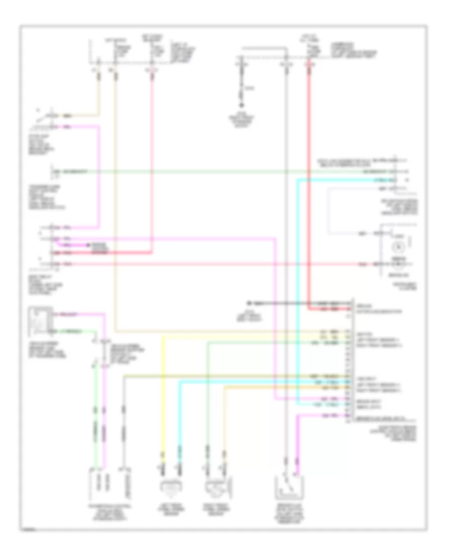
Anti-lock Brake Wiring Diagrams, without Traction Control for GMC Yukon Denali 2002
List of elements for Anti-lock Brake Wiring Diagrams, without Traction Control for GMC Yukon Denali 2002:
- A4 c1
- Abs fuse 60a
- Abs ind
- Body relay block (under left side of dash, near kick panel)
- Brake fluid level sw in
- Brake fluid level switch (on left side of brake fluid reservoir)
- Brake fuse 10a
- Brake ind
- Brake input
- C8 a
- Data link connector (dlc) (below steering column)
- Electronic brake control module (ebcm) (on left side of inner frame)
- Engine control system
- F6 c3
- F7 c2
- G105 (right front of engine block)
- G110 (left front body mount)
- Ground
- Hot at all times
- Hot in run
- Hot in run or start
- Ign 1 fuse 10a
- Ignition
- Instrument cluster
- Left front sensor (+)
- Left front sensor (-)
- Left front wheel speed sensor
- Left i/p fuse block (on lower left side of dash)
- Logic
- Motor & solenoid pwr
- Nca
- Pnk
- Powertrain control module (pcm) (on left front of engine compt)
- Red
- Right front sensor (+)
- Right front sensor (-)
- Right front wheel speed sensor
- S102
- Serial data
- Splice pack sp205 (on left side of dash, behind headlamp switch)
- Stoplamp switch (on top of brake pedal bracket)
- Tan
- Transfer case shift control module (left side of dash, behind headlamp switch)
- Underhood fuse block (at left side of engine compt, near battery)
- Vehicle speed sensor (vss) (on top left side of transfer case)
- Vehicle speed sensor adapter (4wd only) (on left side of trans)
- Vss high
- Vss input
- Vss low
- Vss output