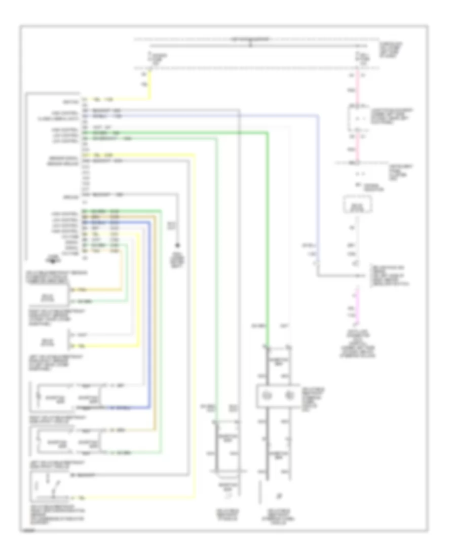
SUPPLEMENTAL RESTRAINTS
Supplemental Restraint Wiring Diagram for GMC Yukon Denali 2002
List of elements for Supplemental Restraint Wiring Diagram for GMC Yukon Denali 2002:
- A10
- A11
- A12
- A13
- A14
- A15
- A16
- A17
- A18
- Air bag fuse 15a
- Air bag indicator
- Case ground
- Class 2 serial data
- Data link connector (dlc) (partial) (under left side of dash, below steering column)
- Fuse block (on lower left side of dash)
- G304 (under driver seat)
- Ground
- High control
- Hot in run & start
- Ign 1 fuse 10a
- Ignition
- Inflatable restraint front end discrimininating sensor (on underside of radiator support)
- Inflatable restraint ip module
- Inflatable restraint sensing & diagnostic module (under driver's seat)
- Inflatable restraint steering wheel module
- Inflatable restraint steering wheel module coil
- Instrument panel cluster (ipc)
- Junction block-body (under left side of dash, near left kick panel)
- Left inflatable restraint side impact module
- Left inflatable restraint side impact sensor (in left door lower side panel)
- Low control
- Nca
- Pnk
- Right inflatable restraint side impact module
- Right inflatable restraint side impact sensor (in right door lower side panel)
- Sensor ground
- Sensor signal
- Shorting bar
- Signal
- Solid state
- Splice pack 205 (sp205) (on left side of dash, behind headlamp switch)
- Tan
- Voltage
 English