ANTI-LOCK BRAKES
Anti-lock Brakes Wiring Diagram (1 of 2) for Pontiac Vibe GT 2010

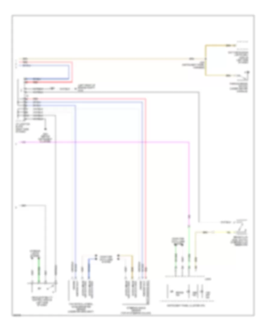
List of elements for Anti-lock Brakes Wiring Diagram (1 of 2) for Pontiac Vibe GT 2010:
- (right front of engine compt) g106
- Abs 1 fuse 50a
- Abs 3 fuse 30a
- Battery positive volt
- Body control module
- Bus +
- Bus -
- Computer data lines system
- Ecu-b fuse 10a
- Ecu-ig 1 fuse 6 10a
- Electronic brake control module (ebcm) (right side of engine compartment)
- Ground
- Hot at all times
- Hot w/ ig 1 relay energized
- I/p fuse block (left end of dash)
- Ignition voltage
- J203
- Left front wheel speed sensor (left front wheel hub assembly)
- Left i/p junction block (left side of dash)
- Left rear wheel speed sensor (left rear wheel hub assembly)
- Lf wheel spd sens ctrl
- Lf wheel spd sens sig
- Lr wheel spd sens ctrl
- Lr wheel spd sens sig
- Pnk
- Red
- Rf wheel spd sens ctrl
- Rf wheel spd sens sig
- Right front wheel speed sensor (right front wheel hub assembly)
- Right rear wheel speed sensor (right rear wheel hub assembly)
- Rr wheel spd sens ctrl
- Rr wheel spd sens sig
- Sensor check input
- Serial data bus+
- Serial data bus-
- Stop fuse 10a
- Stop lamp sw sig (batt)
- Stop lamp switch (left side of dash)
- Underhood fuse block (left side of engine compartment)
- Veh spd sens sig
- Veh stability ctrl sw in
- X13
Anti-lock Brakes Wiring Diagram (2 of 2) for Pontiac Vibe GT 2010
List of elements for Anti-lock Brakes Wiring Diagram (2 of 2) for Pontiac Vibe GT 2010:
- (left front of engine compt) g102
- Abs ind
- Batt positive volt
- Brake fluid level switch (in brake fluid reservoir)
- Brake ind
- Computer data lines system
- Daytime running lights (drl) module (left side of dash)
- G201 (behind instrument cluster)
- Ground
- Hi spd gmlan
- I/p junction block (right side of dash)
- Ignition volt
- Instrument panel cluster (ipc)
- Interior lights system
- J104
- J220 (instrument panel harness)
- Logic
- Parking brake switch (under center console)
- Red
- Ser data bus+
- Ser data bus-
- Steering angle sensor (top of steering column)
- Vehicle stability control module (left side of dash)
- Vsc off ind
- Yaw rate & lateral accelerometer sensor (under driver's seat)