TRANSMISSION
1.8L VIN 8
1.8L VIN 8, A/T Wiring Diagram for Pontiac Vibe GT 2010

List of elements for 1.8L VIN 8, A/T Wiring Diagram for Pontiac Vibe GT 2010:
- (engine harness) j111
- (engine harness) j226
- Automatic transmission fluid temperature (tft) sensor
- Automatic transmission input shaft speed (iss) sensor (on transmission)
- Automatic transmission shift lever position indicator
- Backup lamp sw sig
- Computer data lines system
- Ecu-ig 2 fuse 7 10a
- Etcs fuse 10a
- Exterior lights system
- G102 (left front of engine compt)
- Gmlan serial data bus+
- Gmlan serial data bus-
- Ground
- High signal
- Hot at all times
- Hot w/ ign 1 relay energized
- I/p fuse block (left end of dash)
- J104
- J116
- Low reference
- Low signal
- Park/neutral position (pnp) switch (on transmission)
- Pnk
- Pnp sw drive sig
- Pnp sw neutral sig
- Pnp sw second sig
- Pnp switch low sig
- Pnp switch park sig
- Powertrain control module (pcm) (left side of engine compt)
- Red
- S1 control
- S2 control
- Shift lock relay ctrl
- Shift solenoid valve (ssv) s1
- Shift solenoid valve (ssv) s2
- Shift solenoid valve (ssv) slt
- Shift solenoid valve (ssv) slu
- Shift solenoid valve (ssv) st
- Slt high control
- Slt low control
- Slu high control
- Slu low control
- Tft sensor signal
- Transmission connector
- Underhood fuse block (left side of engine compt)
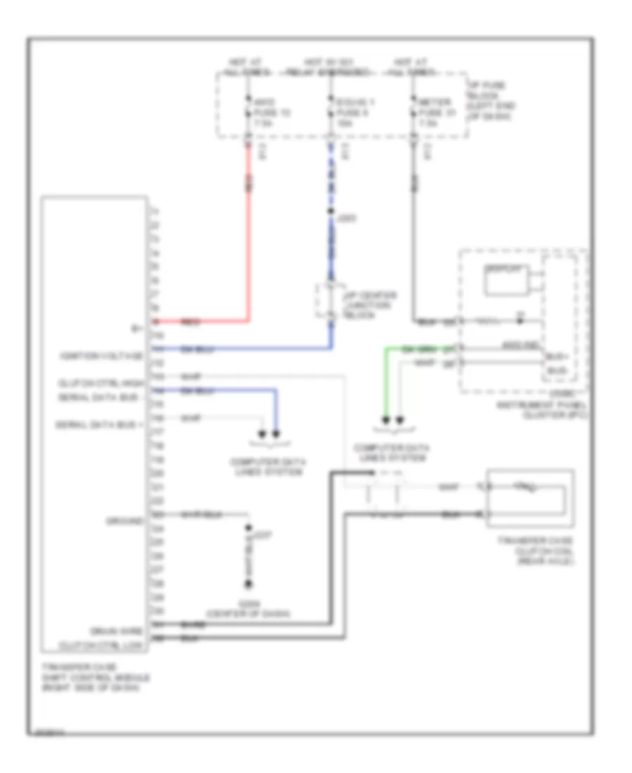
1.8L VIN 8, Transfer Case Wiring Diagram for Pontiac Vibe GT 2010
List of elements for 1.8L VIN 8, Transfer Case Wiring Diagram for Pontiac Vibe GT 2010:
- 4wd fuse 13 7.5a
- 4wd ind
- Bare
- Bus+
- Bus-
- Clutch ctrl high
- Clutch ctrl low
- Computer data lines system
- Display
- Drain wire
- Ecu-ig 1 fuse 6 10a
- G204 (center of dash)
- Ground
- Hot at all times
- Hot w/ ig1 relay energized
- I/p center junction block
- I/p fuse block (left end of dash)
- Ignition voltage
- Instrument panel cluster (ipc)
- J203
- Logic
- Meter fuse 31 7.5a
- Red
- Serial data bus +
- Serial data bus -
- Transfer case clutch coil (rear axle)
- Transfer case shift control module (right side of dash)
- X12
- X13
2.4L VIN 0
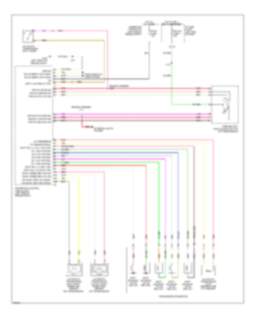
2.4L VIN 0, A/T Wiring Diagram, 4 Speed A/T for Pontiac Vibe GT 2010
List of elements for 2.4L VIN 0, A/T Wiring Diagram, 4 Speed A/T for Pontiac Vibe GT 2010:
- (engine harness) j111
- (engine harness) j226
- Automatic transmission fluid temperature (tft) sensor
- Automatic transmission input shaft speed (iss) sensor (on transmission)
- Automatic transmission output shaft speed (oss) sensor (on transmission)
- Automatic transmission shift lever
- Backup lamp sw sig
- Computer data lines system
- Ecu-ig 2 fuse 7 10a
- Etcs fuse 10a
- Exterior lights system
- G102 (left front of engine compt)
- Gmlan serial data bus+
- Gmlan serial data bus-
- Ground
- Hot at all times
- Hot w/ ign 1 relay energized
- I/p fuse block (left end of dash)
- Inp shaft spd high signal
- Inp shaft spd low signal
- J104
- J116
- Low reference
- Park/neutral position (pnp) switch (on transmission)
- Pnk
- Pnp sw drive sig
- Pnp sw neutral sig
- Pnp sw second sig
- Pnp switch low sig
- Pnp switch park sig
- Powertrain control module (pcm) (left side of engine compt)
- Red
- Shaft speed sen high sig
- Shaft speed sen low sig
- Shift lock relay ctrl
- Shift sol valve s4 ctrl
- Shift sol vlv dsl ctrl
- Shift sol vlv sl1 low ctrl
- Shift solenoid valve (ssv) dsl
- Shift solenoid valve (ssv) s4
- Shift solenoid valve (ssv) sl1
- Shift solenoid valve (ssv) sl2
- Shift solenoid valve (ssv) slt
- Sl1 high control
- Sl2 high control
- Sl2 low control
- Slt high control
- Slt low control
- Tft sensor signal
- Transmission connector
- Underhood fuse block (left side of engine compt)
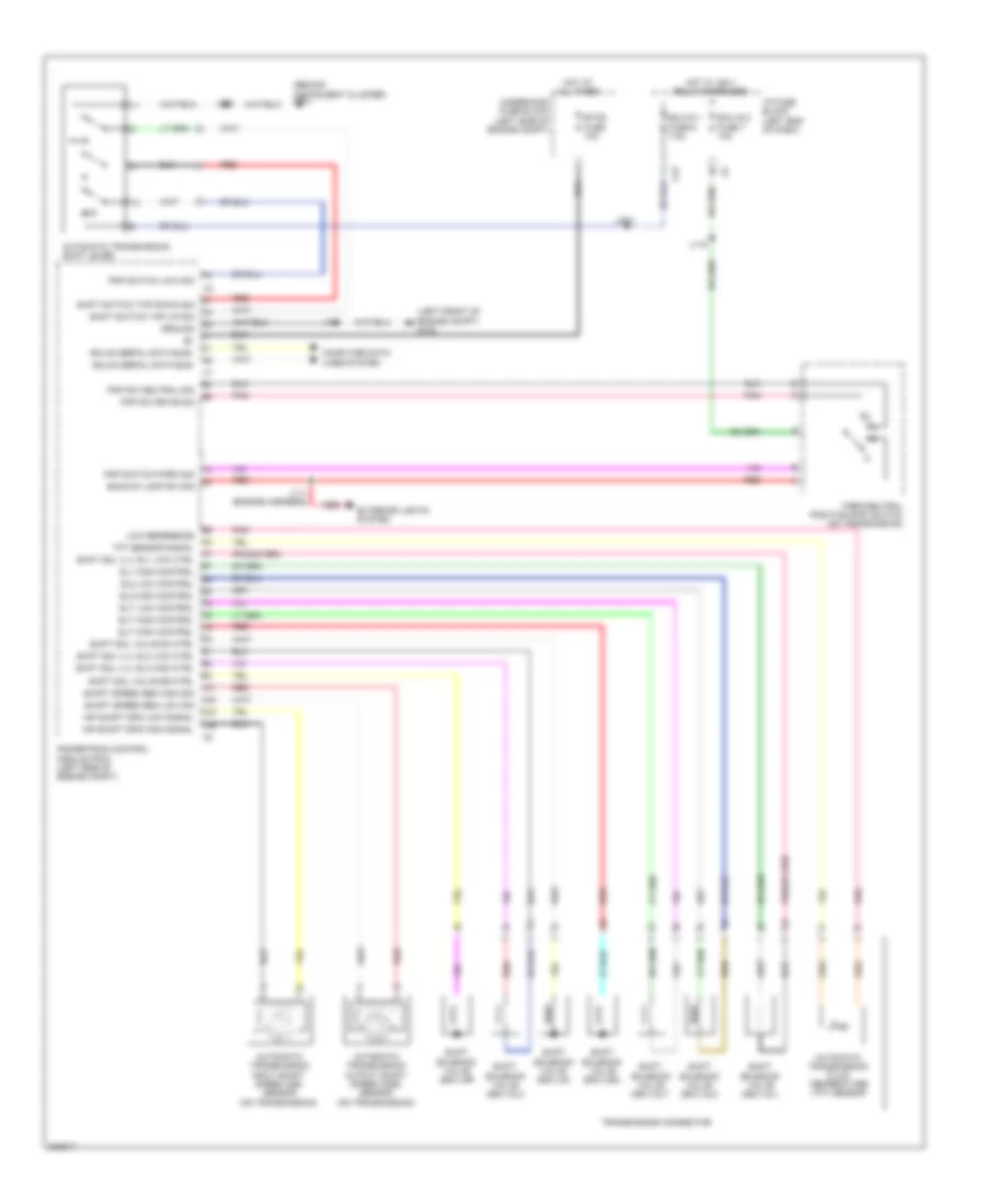
2.4L VIN 0, A/T Wiring Diagram, 5 Speed A/T for Pontiac Vibe GT 2010
List of elements for 2.4L VIN 0, A/T Wiring Diagram, 5 Speed A/T for Pontiac Vibe GT 2010:
- (behind instrument cluster) g201
- (left front of engine compt) g102
- Automatic transmission fluid temperature (tft) sensor
- Automatic transmission input shaft speed (iss) sensor (on transmission)
- Automatic transmission output shaft speed (oss) sensor (on transmission)
- Automatic transmission shift lever
- Backup lamp sw sig
- Computer data lines system
- Ecu-ig 1 fuse 6 7.5a
- Ecu-ig 2 fuse 7 10a
- Etcs fuse 10a
- Exterior lights system
- Gmlan serial data bus+
- Gmlan serial data bus-
- Ground
- Hot at all times
- Hot w/ ign 1 relay energized
- I/p fuse block (left end of dash)
- Inp shaft spd high signal
- Inp shaft spd low signal
- J104
- J111 (engine harness)
- J116
- J203
- J205
- Low reference
- Park/neutral position (pnp) switch (on transmission)
- Pnk
- Pnp sw drive sig
- Pnp sw neutral sig
- Pnp switch low sig
- Pnp switch park sig
- Powertrain control module (pcm) (left side of engine compt)
- Red
- S-d
- Shaft speed sen high sig
- Shaft speed sen low sig
- Shift sol valve s4 ctrl
- Shift sol valve sr ctrl
- Shift sol vlv sl1 low ctrl
- Shift sol vlv sl3 high ctrl
- Shift sol vlv sl3 low ctrl
- Shift solenoid valve (ssv) dsl
- Shift solenoid valve (ssv) s4
- Shift solenoid valve (ssv) sl1
- Shift solenoid valve (ssv) sl2
- Shift solenoid valve (ssv) sl3
- Shift solenoid valve (ssv) slt
- Shift solenoid valve (ssv) sr
- Shift switch tap down sig
- Shift switch tap up sig
- Sl1 high control
- Sl2 high control
- Sl2 low control
- Slt high control
- Slt low control
- Tft sensor signal
- Transmission connector
- Underhood fuse block (left side of engine compt)
- X13
2.4L VIN 0, Transfer Case Wiring Diagram for Pontiac Vibe GT 2010
List of elements for 2.4L VIN 0, Transfer Case Wiring Diagram for Pontiac Vibe GT 2010:
- 4wd fuse 13 7.5a
- 4wd ind
- Bare
- Bus+
- Bus-
- Clutch ctrl high
- Clutch ctrl low
- Computer data lines system
- Display
- Drain wire
- Ecu-ig 1 fuse 6 10a
- G204 (center of dash)
- Ground
- Hot at all times
- Hot w/ ig1 relay energized
- I/p center junction block
- I/p fuse block (left end of dash)
- Ignition voltage
- Instrument panel cluster (ipc)
- J203
- Logic
- Meter fuse 31 7.5a
- Red
- Serial data bus +
- Serial data bus -
- Transfer case clutch coil (rear axle)
- Transfer case shift control module (right side of dash)
- X12
- X13