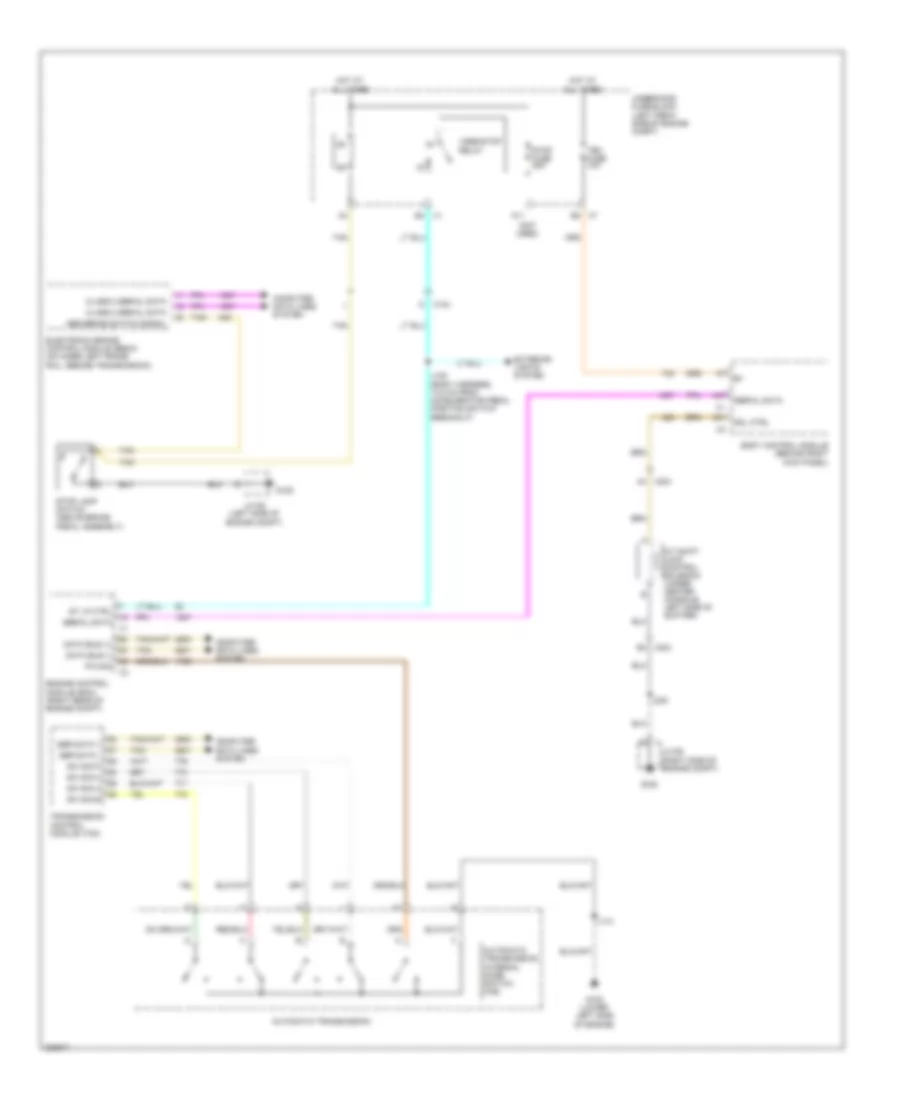
SHIFT INTERLOCK
Shift Interlock Wiring Diagram for GMC Canyon 2011
List of elements for Shift Interlock Wiring Diagram for GMC Canyon 2011:
- (not used)
- A/t shift lock control solenoid (under center console, left side of shifter)
- A11
- A31
- A4 x204
- A47
- Abs brake switch signal
- Automatic transmission
- Automatic transmission internal mode switch (ims)
- B2 x7
- B4 x1
- B4 x204
- Body control module (behind right kick panel)
- Class 2 serial data
- Computer data lines system
- Data bus (+)
- Data bus (-)
- Electronic brake control module (ebcm) (on inner left frame rail, beside transmission)
- Engine control module (ecm) (right rear of engine compt)
- Exterior lights system
- G102 (lower left side of engine)
- G105
- G106
- Hot at all times
- J100 (body harness, 14.5 cm from accelerator pedal position switch breakout)
- J110
- J200
- Jx105 (left side of engine compt)
- Jx106 (right side of engine compt)
- M x104
- P/n sig
- Ser data +
- Ser data -
- Serial data
- Sol ctrl
- St lp ctrl
- Stop fuse 20a
- Stop lamp switch (above brake pedal assembly)
- Sw sig a
- Sw sig b
- Sw sig c
- Sw sig p
- Tan
- Tbc fuse 10a
- Transmission control module (tcm)
- Underhood fuse block (left front side of engine compt)
- Vses/stop relay
 English