ENGINE PERFORMANCE
2.0L TURBO
2.0L Turbo, Engine Performance Wiring Diagram (1 of 4) for Saab 9-3 Turbo4 2011

List of elements for 2.0L Turbo, Engine Performance Wiring Diagram (1 of 4) for Saab 9-3 Turbo4 2011:
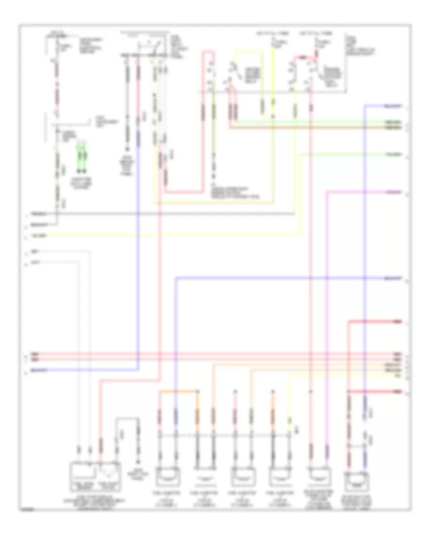
2.0L Turbo, Engine Performance Wiring Diagram (2 of 4) for Saab 9-3 Turbo4 2011
List of elements for 2.0L Turbo, Engine Performance Wiring Diagram (2 of 4) for Saab 9-3 Turbo4 2011:
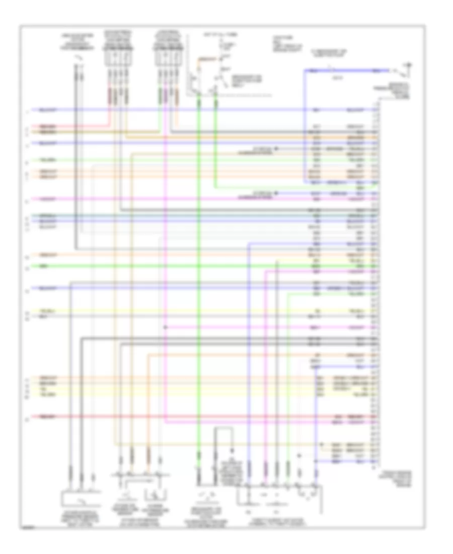
2.0L Turbo, Engine Performance Wiring Diagram (3 of 4) for Saab 9-3 Turbo4 2011
List of elements for 2.0L Turbo, Engine Performance Wiring Diagram (3 of 4) for Saab 9-3 Turbo4 2011:
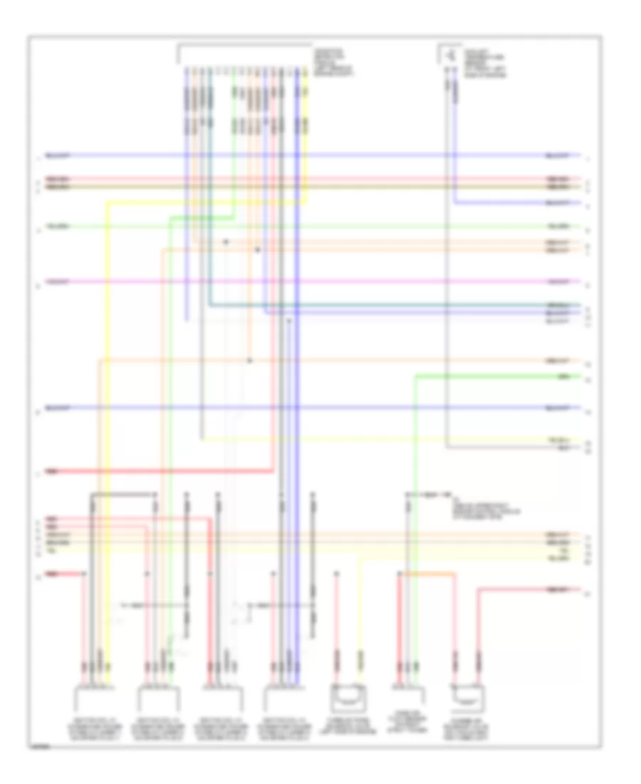
2.0L Turbo, Engine Performance Wiring Diagram (4 of 4) for Saab 9-3 Turbo4 2011
List of elements for 2.0L Turbo, Engine Performance Wiring Diagram (4 of 4) for Saab 9-3 Turbo4 2011: