POWER DISTRIBUTION
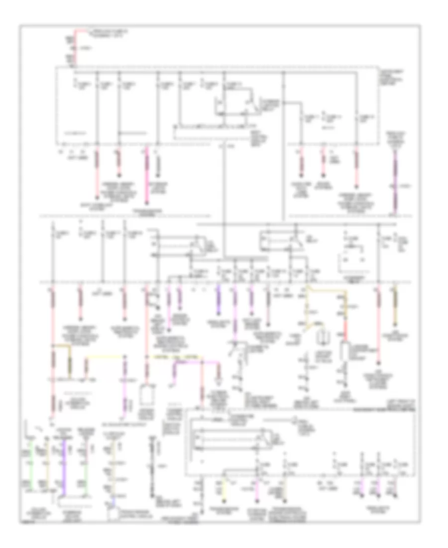
Power Distribution Wiring Diagram (1 of 3) for Saab 9-3 Turbo4 2011

List of elements for Power Distribution Wiring Diagram (1 of 3) for Saab 9-3 Turbo4 2011:
- (left front of engine compt) engine bay electrical center
- (or red)
- +50 relay
- 87a
- A/c compressor relay
- Alternator
- Anti-lock brakes system
- B11
- B12
- B13
- B14
- B15
- B16
- Battery
- Battery sensor
- Cooling fans system
- Electronic power steering system
- Engine controls system
- Exterior lights system
- F20
- F22
- F24
- F27
- F29
- F30
- F34
- F35
- F36
- F43
- Fuel pump relay
- Full/half speed windshield wiper relay
- Fuse 12 10a
- Fuse 15 30a
- Fuse 16 30a
- Fuse 17 30a
- Fuse 18 30a
- Fuse 2 10a
- Fuse 2 20a
- Fuse 24 20a
- Fuse 25 20a
- Fuse 26 30a
- Fuse 3 10a
- Fuse 3 20a
- Fuse 30a
- Fuse 4 30a
- Fuse n/a
- G2 (on side of left-hand structural member on connector console)
- G25 (2.0l turbo: on transmission)
- G30a (above left front wheel housing)
- H24-2
- Heated oxygen sensor relay
- High pressure headlamp washer fluid pump relay
- Horn relay
- Horns system
- Integ- rated control module
- M14
- M16
- M24
- M25
- Main fuse box (engine management system) (left front of engine compt)
- Main relay
- Maxi fuse 1 60a
- Maxi fuse 20a
- Maxi fuse 28 40a
- Maxi fuse 29 60a
- Maxi fuse 30 60a
- Maxi fuse 30a
- Maxi fuse 32 60a
- Maxi fuse 33 40a
- Maxi fuse 40a
- Maxi fuse 60a
- Nca
- Power steering/ glow plug fuse holder
- Rear window washer fluid pump relay
- Red
- Secondary air injection pump relay
- Spot- lights relay
- Starter motor
- Starting/ charging & sound systems
- To +15 uec relay (diagram 2 of 3)
- To instrument panel electrical center (diagram 2 of 3)
- To rear electrical center (diagram 3 of 3)
- Transmissions system
- Wind- shield washer fluid pump relay
- Windshield wiper relay
- Wiper/ washer system
- Wiper/washer system
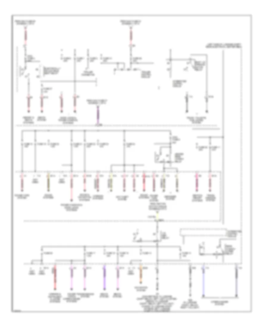
Power Distribution Wiring Diagram (2 of 3) for Saab 9-3 Turbo4 2011
List of elements for Power Distribution Wiring Diagram (2 of 3) for Saab 9-3 Turbo4 2011:
- (left front of engine compt) engine bay electrical center
- (not used)
- +15 ipec relay
- +15 uec relay
- +54 relay
- 15+ on & start output
- A-10
- A/t
- Accessory relay
- Air bag control module
- Air conditioning & instrument cluster systems
- Air conditioning system
- Anti-lock brakes system
- B20
- Body control module (bcm)
- C154
- C155
- C160
- C161
- C31-154
- Cabin 12v socket
- Cigarette lighter
- Column integration module
- Computer data lines system
- Data
- Engine controls system
- Exterior lights system
- F19
- F26
- F28
- F39
- F42
- From fuse 22 (diagram 1 of 3)
- From maxi fuse 30 (diagram 1 of 3)
- From maxi fuse 32 d (diagram 1 of 3)
- Fuse
- Fuse 1 15a
- Fuse 10a
- Fuse 11 15a
- Fuse 12 15a
- Fuse 14 20a
- Fuse 15 30a
- Fuse 16 7.5a
- Fuse 17 7.5a
- Fuse 2 5a
- Fuse 21 7.5a
- Fuse 24 7.5a
- Fuse 3 10a
- Fuse 30a
- Fuse 5 7.5a
- Fuse 5a
- Fuse 6 7.5a
- Fuse 7 20a
- Fuse 7.5a
- Fuse 8 30a
- Fuse 9 10a
- G31 (above right front wheel housing)
- G34p (right kick panel)
- G40 (behind left side of dash)
- G41 (in instrument space, right of knee member)
- Gnd
- H102-1
- H24-2
- H33-1
- Headlights system
- I-bus
- Ignition switch module
- Instrument panel electrical center
- Integrated control module
- Interior lighting relay
- K16
- K25
- K30
- Lighting socket 12v bulb
- Locking pin released
- Luggage compartment 12v socket
- M/t
- Maxi fuse 40a
- Mirrors, memory, door locks , power windows & interior lights systems
- Mirrors, memory, door locks, power windows & interior lights systems
- Not used
- P15-44
- P30-61
- Red
- Release locking pin
- Shift interlock system
- Sound systems
- Starting/ charging system
- Steering column lock unit
- Tcs/esp control module
- To rear electrical center (diagram 3 of 3)
- Transmissions , engine controls & electronic power steering systems
- Transmissions system
- Trionic engine control module
- X+ off & on output
Power Distribution Wiring Diagram (3 of 3) for Saab 9-3 Turbo4 2011
List of elements for Power Distribution Wiring Diagram (3 of 3) for Saab 9-3 Turbo4 2011:
- (left side of luggage compt) rear electrical center (rec)
- (not used)
- +15 rec relay
- 10a
- 40a
- 87a
- Anti-theft system
- B1-a
- B1-b
- B1-c
- B1-d
- B2-b
- B2-d
- Boot lid opening motor relay
- Defogger system
- Door locks & power windows systems
- Electrically adjustable seat relay
- From ignition switch module (diagram 2 of 3)
- From maxi fuse 29 (diagram 1 of 3)
- From maxi fuse 34 (diagram 1 of 3)
- From maxi fuse 37 (diagram 1 of 3)
- Fuse 10 30a
- Fuse 11 n/a
- Fuse 13
- Fuse 14 15a
- Fuse 15 15a
- Fuse 16 15a
- Fuse 17 7.5a
- Fuse 18 15a
- Fuse 19
- Fuse 20 7.5a
- Fuse 21 7.5a
- Fuse 22 30a
- Fuse 23 n/a
- Fuse 24 10a
- Fuse 25 30a
- Fuse 26 30a
- Fuse 27
- Fuse 28
- Fuse 6 30a
- Fuse 7 30a
- Fuse 8 20a
- G29 (in luggage compt, below right taillight)
- G3 (convertible: in luggage compt below left light cluster) (sedan: in luggage compt, below left taillight) (wagon: in luggage compt on rear left luggage compt floor support)
- Heated rear window relay
- Integrated control module
- Maxi fuse 4 40a
- Maxi fuse 5
- Memory & seats systems
- Mirrors & instrument cluster systems
- Navigation system
- Power tops & wiper/washer systems
- Power tops system
- Power windows & door locks systems
- R-a
- R-b
- R1-b
- Rear window wiper relay
- Red
- Seats & memory systems
- Seats system
- Sound & navigation systems
- Sound systems
- T-a
- T-c
- T-d
- Trailer connector
- Trailer control module
- Trans- missions system
- Transmissions system
- Trunk, tailgate, fuel doors system
- Warning systems
- Wiper/washer system