AIR CONDITIONING
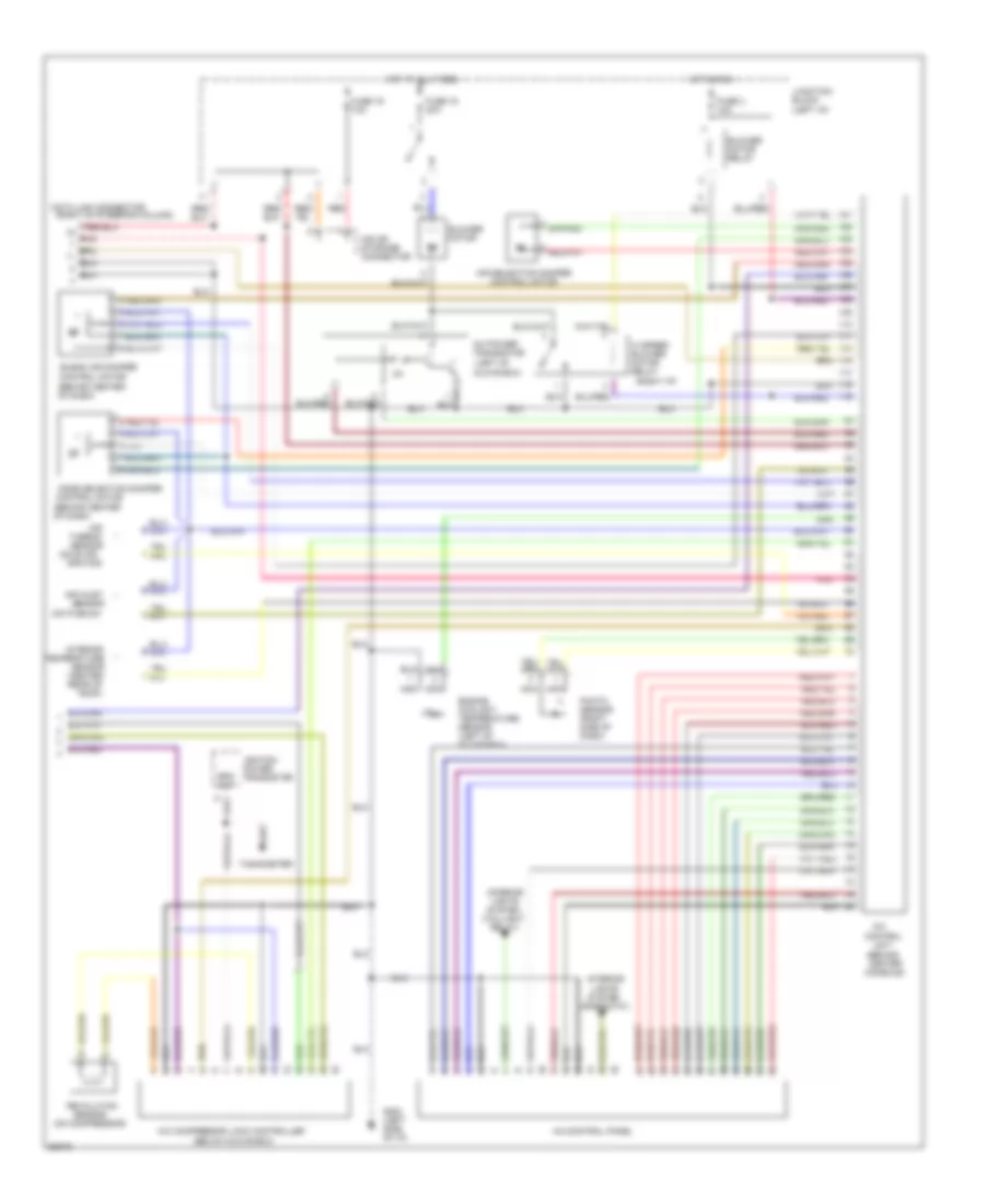
A/C Wiring Diagram, Automatic (1 of 2) for Mitsubishi 3000GT 1994

List of elements for A/C Wiring Diagram, Automatic (1 of 2) for Mitsubishi 3000GT 1994:
A/C Wiring Diagram, Automatic (2 of 2) for Mitsubishi 3000GT 1994
List of elements for A/C Wiring Diagram, Automatic (2 of 2) for Mitsubishi 3000GT 1994:
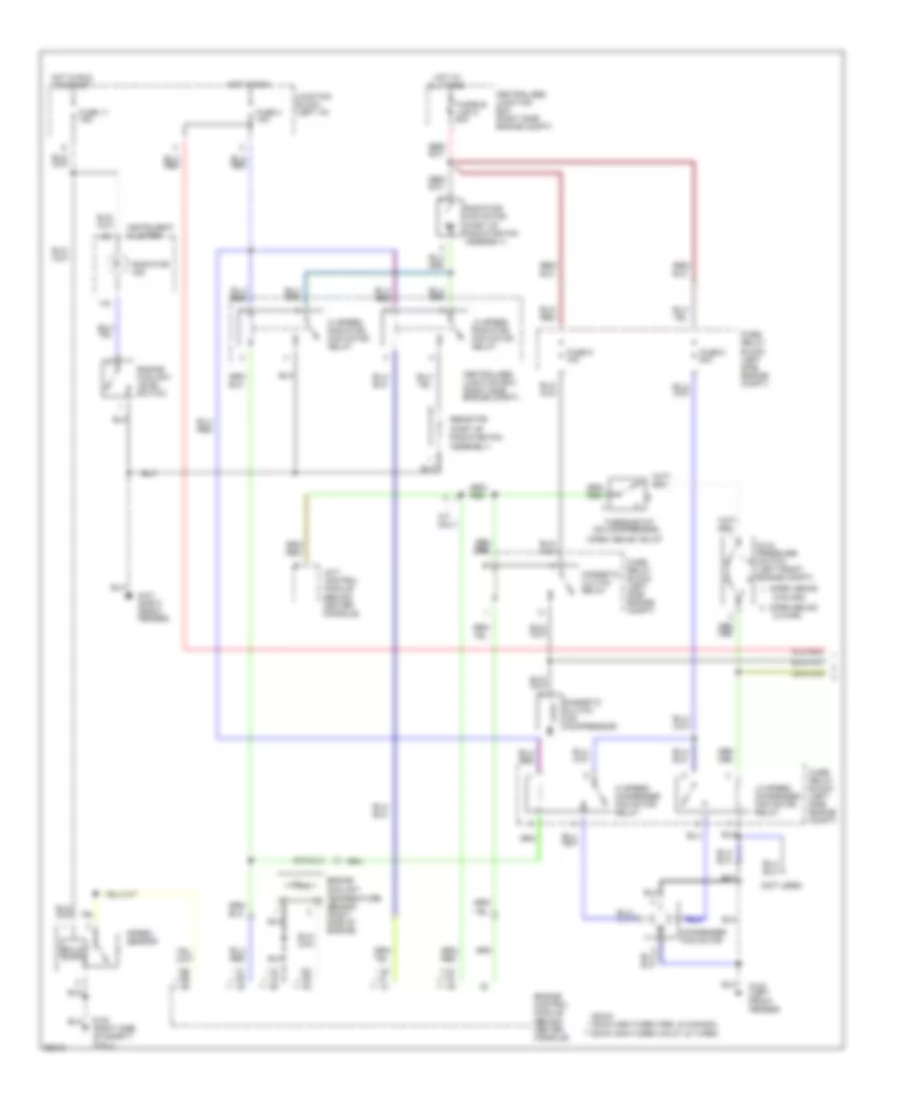
A/C Wiring Diagram, Manual (1 of 2) for Mitsubishi 3000GT 1994
List of elements for A/C Wiring Diagram, Manual (1 of 2) for Mitsubishi 3000GT 1994:
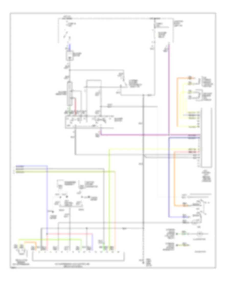
A/C Wiring Diagram, Manual (2 of 2) for Mitsubishi 3000GT 1994
List of elements for A/C Wiring Diagram, Manual (2 of 2) for Mitsubishi 3000GT 1994:
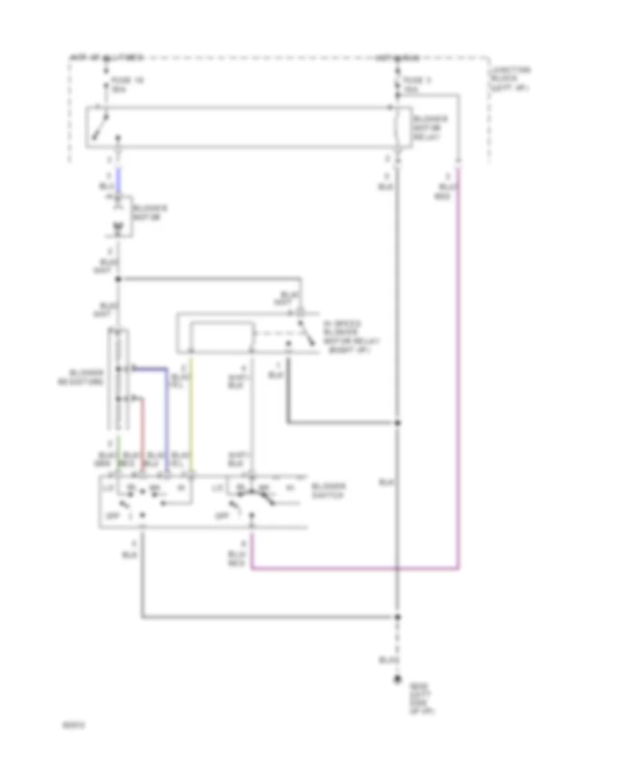
Heater Wiring Diagram for Mitsubishi 3000GT 1994
List of elements for Heater Wiring Diagram for Mitsubishi 3000GT 1994: