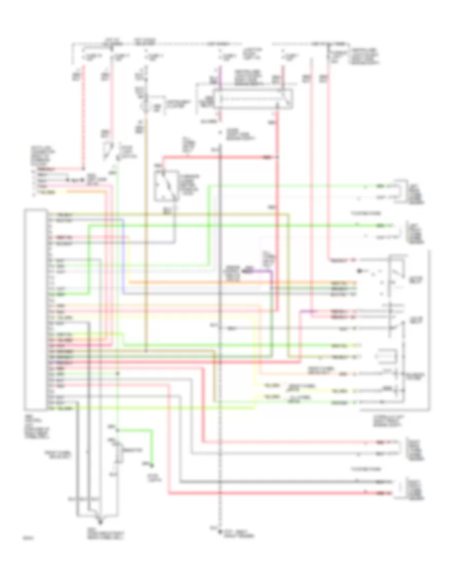
ANTI-LOCK BRAKES
Anti-lock Brake Wiring Diagrams for Mitsubishi 3000GT 1994
List of elements for Anti-lock Brake Wiring Diagrams for Mitsubishi 3000GT 1994:
- (awd)
- (right
- Abs
- Abs control
- Abs ind.
- All times
- All- wheel drive only
- All-wheel
- Centralized junction box (right side engine compt)
- Data link connector (right of steering column)
- Diode (right side engine compt)
- Drive
- Drive only
- Engine control module (pin 44)
- Front-wheel
- Front-wheel drive only
- Fuse 11 15a
- Fuse 17 15a
- Fuse 19 10a
- Fuse 3 10a
- Fuse 7 10a
- Fusible link 7 60a
- G sensor (under center console)
- G101 (front fender)
- G202 (left side of i/p)
- G401 (forward of right rear wheelwell)
- Hot at
- Hot at all times
- Hot in run
- Hot in run or start
- Hydraulic unit (right front engine compt)
- Instrument cluster
- Junction block (left i/p)
- Left front wheel speed sensor
- Left rear wheel speed sensor
- Motor relay
- Pnk
- Power relay
- Red
- Resistor
- Right front wheel speed sensor
- Right rear wheel speed sensor
- Solenoid valves
- Stop light switch
- Stop lights
- Twisted pairs
- Unit (forward of right rear wheelwell)
- Valve relay
 English