ANTI-THEFT
Forced Entry Wiring Diagram (1 of 2) for Mazda 5 Touring 2013

List of elements for Forced Entry Wiring Diagram (1 of 2) for Mazda 5 Touring 2013:
- (if equipped)
- (under driver's seat) g17
- (under passenger's seat) g14
- 0940-101a
- 0940-101c
- 0940-101d
- 0940-101e
- 0940-101f
- Bcm (under right center of dash)
- C-05
- C-17
- C-18
- C-20
- C-30
- C-31
- C-32
- Computer data lines system
- D lock fuse 20a
- Front door latch switch
- Front door lock- link switch
- Fuse block (right end of dash)
- G02 (left front of engine compt)
- G11 (right end of dash)
- G16 (left side of luggage compt)
- Hood latch switch (center front of engine compt)
- Hot at all times
- Hot in on or start
- J/c c-42 (right side of dash)
- J/c c-44
- J/c g02
- J/c g11
- Key reminder switch (part of ignition switch assembly)
- Keyless receiver
- Left sliding door lock-
- Liftgate opener switch
- Link switch
- Lock
- Meter fuse 10a
- Relay & fuse block (left rear of engine compt)
- Right front door latch & lock actuator
- Right sliding door lock actuator
- Right sliding door lock-
- Room fuse 15a
- Unlock
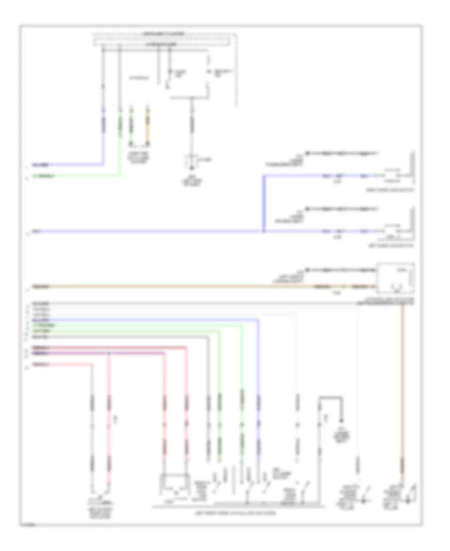
Forced Entry Wiring Diagram (2 of 2) for Mazda 5 Touring 2013
List of elements for Forced Entry Wiring Diagram (2 of 2) for Mazda 5 Touring 2013:
- (left "c" pillar)
- (under
- C-20
- C-29
- C-30
- C-32
- Computer data lines system
- Door ind
- Driver's seat)
- Front door latch switch
- Front door lock- link switch
- G09 (left side of dash)
- G14 (under passenger's seat)
- G16 (left side of
- G17
- G17 (under driver's seat)
- Instrument cluster
- J/c g09
- Key cylinder switch
- Left door lock switch
- Left front door latch & lock actuator
- Left sliding door lock actuator
- Left sliding door switch
- Liftgate lock actuator (bottom center of liftgate)
- Lock
- Luggage compt)
- Microcomputer
- Right door lock switch
- Right sliding door switch (right "c" pillar)
- Security ind
- Unlock
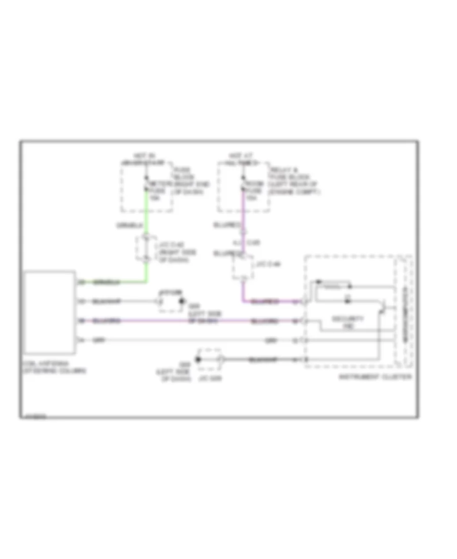
Immobilizer Wiring Diagram for Mazda 5 Touring 2013
List of elements for Immobilizer Wiring Diagram for Mazda 5 Touring 2013:
- (right side of dash)
- Aj c-05
- Coil antenna (steering column)
- Fuse block (right end of dash)
- G09 (left side of dash)
- Hot at all times
- Hot in on or start
- Instrument cluster
- J/c c-42
- J/c c-44
- J/c g09
- Meter fuse 10a
- Microcomputer
- Relay & fuse block (left rear of engine compt)
- Room fuse 15a
- Security ind