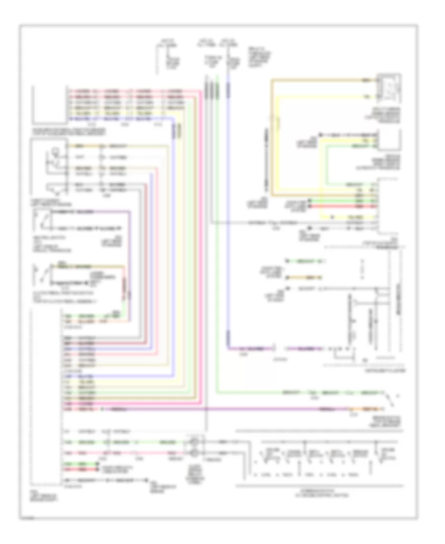
CRUISE CONTROL
Cruise Control Wiring Diagram for Mazda 5 Touring 2013
List of elements for Cruise Control Wiring Diagram for Mazda 5 Touring 2013:
- (left side of manual transaxle)
- (under passenger's seat) g14
- (w/ cruise control switch)
- 0140-101a
- 0140-101b
- 0922-201
- 0922-202
- 1ab
- 1ae
- 1ai
- 1aj
- 1am
- 1an
- 1ao
- 1ap
- 1aq
- 1av
- 1bc
- 1bd
- 2ak
- 2al
- 2an
- 2ar
- 2be
- 2bf
- Accelerator pedal position sensor (top of accelerator pedal bracket)
- Brake switch (top of brake pedal bracket)
- C-02
- C-04
- C-05
- C-10
- C-13
- C-69
- Cancel switch
- Clock spring (below steering wheel)
- Clutch pedal position switch (m/t) (top of clutch pedal assembly)
- Computer data lines system
- Cruise (amber) ind
- Cruise off switch
- Cruise on switch
- Eng +b fuse 10a
- G09 (left side of dash)
- G23 (left rear of engine)
- Hot at all times
- Input/turbine speed sensor (top of automatic transaxle)
- Instrument cluster
- J/c c-44
- Microcomputer
- Nca
- Neutral switch (m/t)
- Pcm (left rear of engine compt)
- Pnk
- Red
- Relay & fuse block (left rear of engine compt)
- Resume switch
- Room fuse 15a
- Set(+) switch
- Set(-) switch
- Steering switch
- Stop fuse 10a
- Tcm (top of automatic transaxle)
- Throttle body (left rear of engine)
- Vehicle speed sensor (right side of automatic transaxle)
 English