ANTI-THEFT
Forced Entry Wiring Diagram for Nissan Maxima SL 2004

List of elements for Forced Entry Wiring Diagram for Nissan Maxima SL 2004:
- (at rear of right rear door sill) right rear door switch
- (at right front of engine compartment) ipdm e/r
- (behind right side of dash) m57
- +ig
- 12p m4
- Acc sw
- Anti-pinch serial link
- B7 (at left "b" pillar)
- Bat (f/l)
- Bat (fuse)
- Between full stroke & n
- Body control module (bcm) (near fuse block (j/b))
- Can-h
- Can-l
- Close
- Closed
- Computer data lines system
- Cpu
- Data link connector (below left side of dash)
- Door sw (as)
- Door sw (dr)
- Door sw (rl)
- Door sw (rr)
- E121
- E122
- E124
- E24 (at right side of engine compt)
- Front door lock assembly (key cylinder switch) (at rear of left front door)
- Fuse & fusible link box (at left front of engine compt)
- Fuse 10a
- Fuse 15a
- Fuse block (j/b) (behind left side of dash)
- Fusible link f 50a
- Gnd
- Gnd (power)
- Gnd (signal)
- H/lp hi
- H/lp lo
- Headlamp high relay
- Headlamp low relay
- Headlights system
- Horn (high) (at right front of engine compt)
- Horn (low) (at left front of engine compt)
- Horn relay
- Horn relay (in fuse & fusible link box)
- Hot at all times
- Hot in acc or on
- Hot in on or start
- Ignition relay
- Left front door switch (at front of left front door sill)
- Left rear door switch (at rear of left rear door sill)
- Lock
- Lock switch full stroke
- M18
- M19
- M20
- M61 (behind right side of dash)
- Main power window & door lock/ unlock switch
- Open
- Power window serial link
- Red
- Right front door switch (at front of right front door sill)
- Right front power window switch
- Security ind output
- Security indicator lamp
- Trunk lamp switch & trunk release solenoid (at rear center of luggage lid)
- Trunk status sw
- Unlock
- Unlock switch full stroke
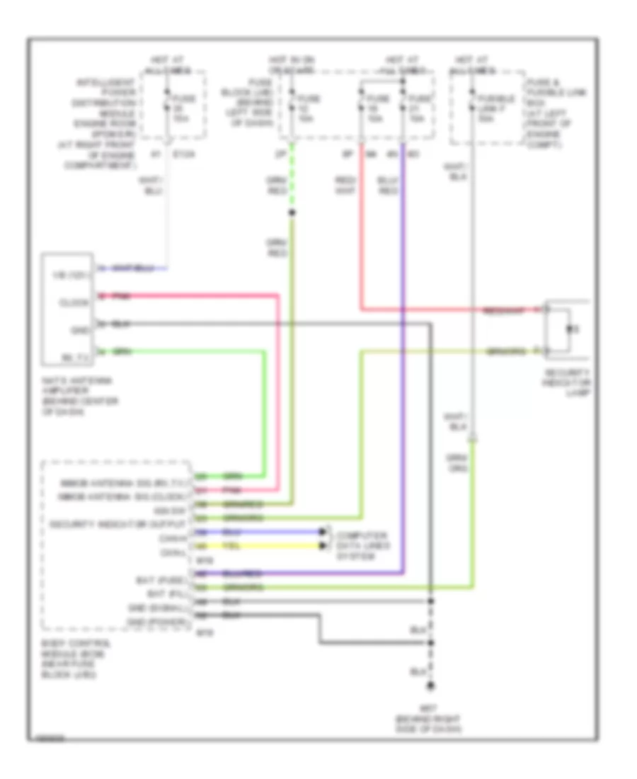
Immobilizer Wiring Diagram for Nissan Maxima SL 2004
List of elements for Immobilizer Wiring Diagram for Nissan Maxima SL 2004:
- 4n m3
- Bat (f/l)
- Bat (fuse)
- Body control module (bcm) (near fuse block (j/b))
- Can-h
- Can-l
- Clock
- Computer data lines system
- E124
- Fuse & fusible link box (at left front of engine compt)
- Fuse 10a
- Fuse 15a
- Fuse block (j/b) (behind left side of dash)
- Fusible link f 50a
- Gnd
- Gnd (power)
- Gnd (signal)
- Hot at all times
- Hot in on or start
- Ign sw
- Immob antenna sig (clock)
- Immob antenna sig (rx,tx)
- Intelligent power distribution module engine room (ipdm e/r) (at right front of engine compartment)
- M18
- M19
- M57 (behind right side of dash)
- Nats antenna amplifier (behind center of dash)
- Pnk
- Rx,tx
- Security indicator lamp
- Security indicator output
- Vb (12v)