TRANSMISSION
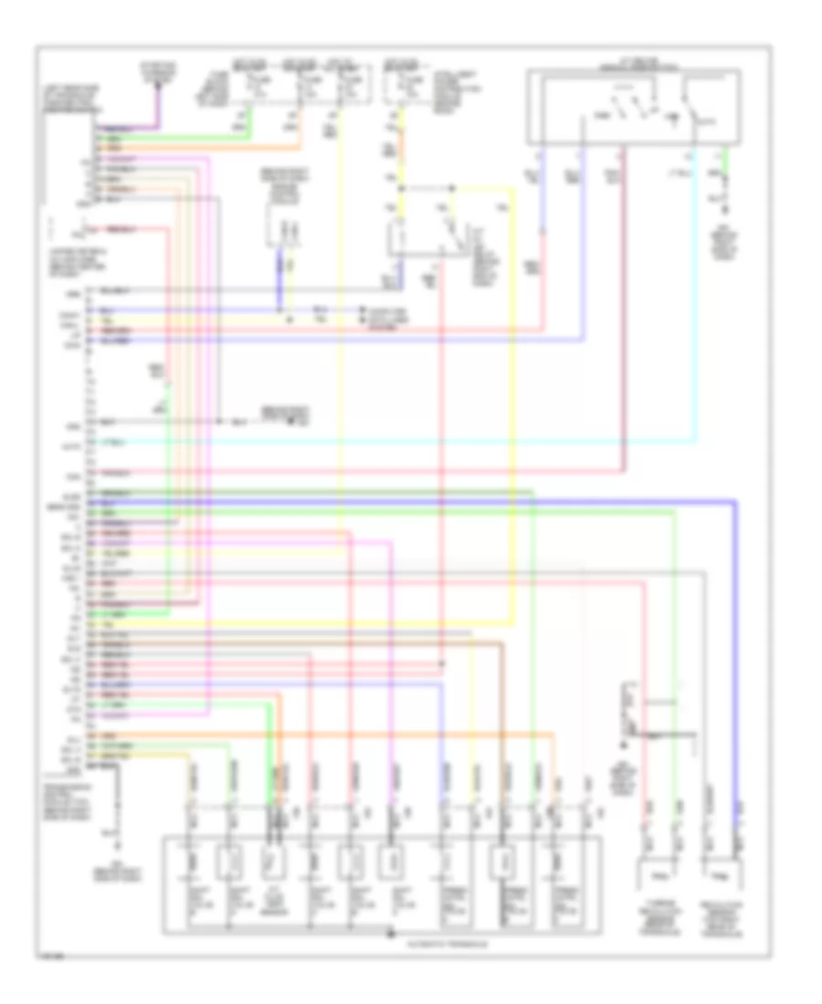
A/T Wiring Diagram, 4 Speed A/T for Nissan Maxima SL 2004

List of elements for A/T Wiring Diagram, 4 Speed A/T for Nissan Maxima SL 2004:
A/T Wiring Diagram, 5 Speed A/T for Nissan Maxima SL 2004
List of elements for A/T Wiring Diagram, 5 Speed A/T for Nissan Maxima SL 2004: