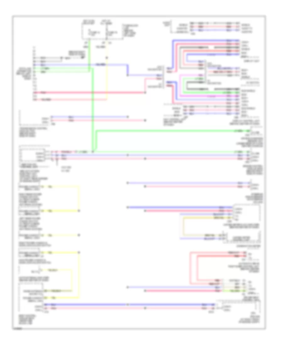
COMPUTER DATA LINES
Computer Data Lines Wiring Diagram for Nissan Maxima SL 2005
List of elements for Computer Data Lines Wiring Diagram for Nissan Maxima SL 2005:
- (behind right side of dash) m57
- Abs actuator & electric unit (control unit) (at right rear corner of engine compt)
- Abs/tcs/vdc control unit
- Air bag diagnosis sensor unit (under rear of floor center console)
- Audio rx
- Audio tx
- Audio unit
- Automatic drive positioner control unit (behind center of dash)
- Av switch
- Body control module (bcm) (near fuse block (j/b))
- Bus +
- Bus -
- Bus shield
- Can-h
- Can-l
- Combination meter
- Cpu
- Data link connector (below left side of dash)
- Diag-k
- Display control unit (behind center of dash)
- Display unit
- Driver seat control unit
- E121
- Engine control module (ecm) (behind right side of dash)
- F56
- Fuse 12 10a
- Fuse 19 10a
- Fuse block (j/b) (behind left side of dash)
- Hot at all times
- Hot in on or start
- Immob antenna sig (rx,tx)
- Ipdm e/r (at right front of engine compt)
- K-line
- Left rear power window switch (w/ front & rear power window anti-pinch system)
- M18
- M35
- M41
- M45
- M49
- M82
- M95
- M97
- Main power window & door lock/unlock switch
- Nats antenna amplifier (behind center of dash)
- Navi control unit (behind center of dash)
- Nca
- Pnk
- Power window serial link
- Red
- Right power window & door lock/unlock switch
- Right rear power window switch (w/ front & rear power window anti-pinch system)
- Rx,tx
- Shield
- Steering angle sensor (on steering column)
- Transmission control module (tcm) (behind right side of dash)
- Unified meter & a/c amplifier (behind center of dash)
- Unified meter control unit
- W/ navigation
- W/ vdc
- W/o navigation
- W/o vdc
 English