COOLING FAN
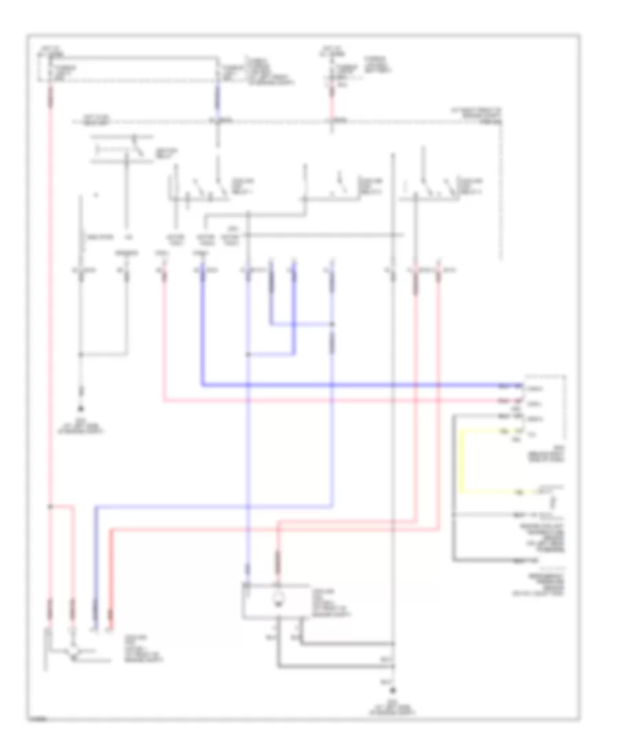
Cooling Fan Wiring Diagram for Nissan Maxima SL 2005
List of elements for Cooling Fan Wiring Diagram for Nissan Maxima SL 2005:
- (at right front of engine compt) ipdm e/r
- +ig
- Can-h
- Can-l
- Cooling fan motor 1 (at front of engine compt)
- Cooling fan motor 2 (at front of engine compt)
- Cooling fan relay 1
- Cooling fan relay 2
- Cooling fan relay 3
- Cpu
- E10
- E118
- E120
- E121
- E123
- E124
- E15 (at left side of engine compt)
- Ecm (behind right side of dash)
- Engine coolant temperature sensor (on left rear of engine)
- F54
- Fuse & fusible link box (at left front of engine compt)
- Fusible link b 80a
- Fusible link box (battery)
- Fusible link k 40a
- Fusible link l 40a
- Gnd (pwr)
- Gnd (sig)
- Gnd-a
- Hot at all times
- Hot in on or start
- Ignition relay
- M82
- Motor fan-1
- Motor fan-2
- Motor fan-3
- Pnk
- Red
- Refrigerant pressure sensor (on a/c liquid tank)
 English