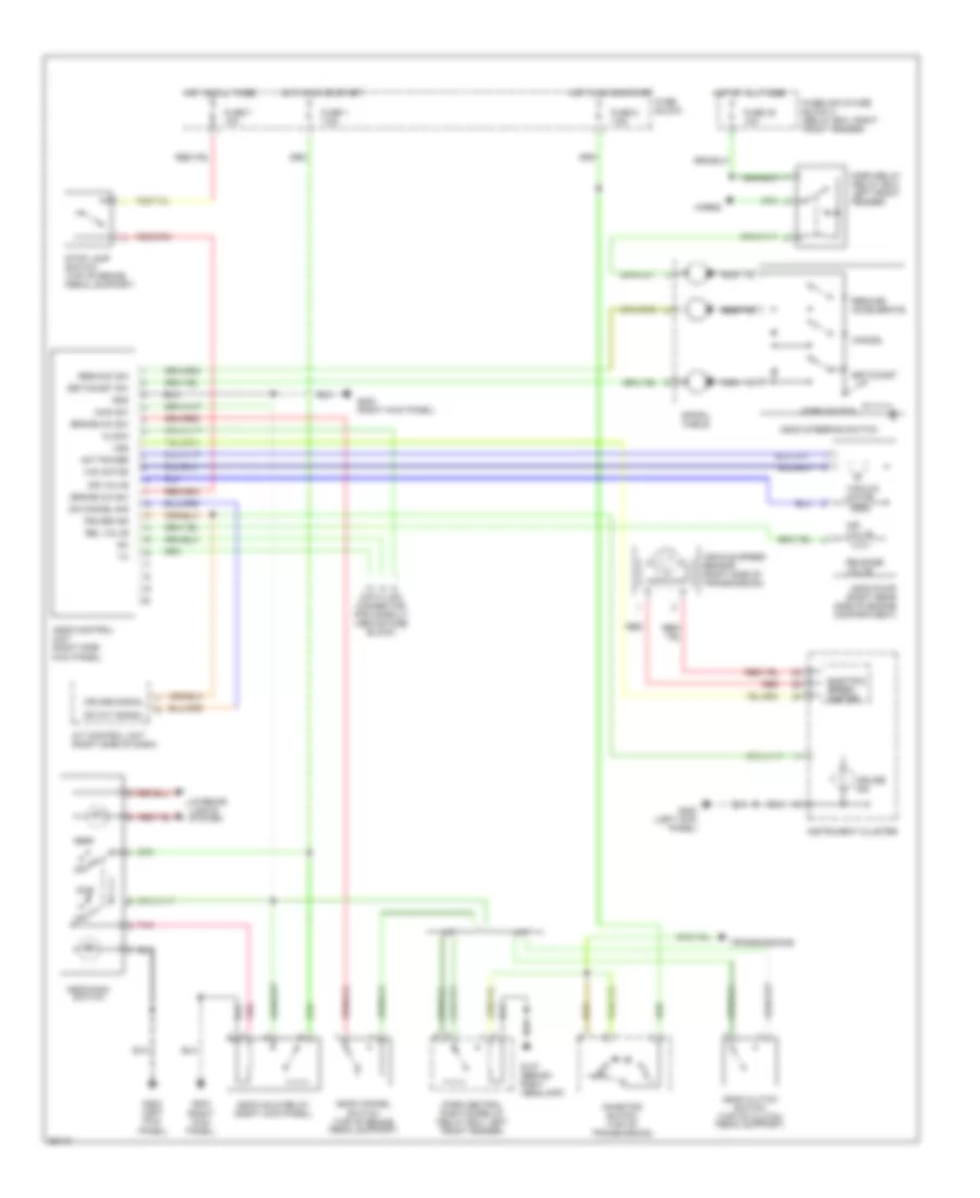
CRUISE CONTROL
Cruise Control Wiring Diagram for Nissan 240SX SE 1995
List of elements for Cruise Control Wiring Diagram for Nissan 240SX SE 1995:
- (right kick panel)
- A/t
- A/t control unit (right side of dash)
- Act power
- Air valve
- Ascd cancel switch (top of brake pedal support)
- Ascd clutch switch (top of clutch pedal support)
- Ascd control unit (right side kick panel)
- Ascd hold relay (right kick panel)
- Ascd main
- Ascd pump (right rear side of engine compartment)
- Ascd steering switch
- Brake n/c sw
- Brake n/o sw
- Cancel
- Clock
- Cruise ind
- Cruise signal
- Data link connector for consult (above fuse block)
- Electric speed- ometer
- Fuse 1 7.5a
- Fuse 2 7.5a
- Fuse 38 10a
- Fuse 7 10a
- Fuse block
- Fuselink & fuse block 2 (relay box, right front fender)
- G107 (behind right headlamp)
- G200 (left kick panel)
- G203
- G203 (right kick panel)
- Gnd
- Horn relay (relay box, left front fender)
- Horn switch
- Horns
- Hot at all times
- Hot in on or start
- Inhibitor switch (top of transmission)
- Instrument cluster
- Interior lights system
- M/t
- Main sw
- Nca
- Od cancel sig
- Od cut signal
- Off
- Park neutral position relay (relay box, left front fender)
- Pnk
- Red
- Rel valve
- Release valve
- Res/acc sw
- Resume/ accelerate
- Set/coast
- Set/coast sw
- Spiral cable
- Stop lamp switch (top of brake pedal support)
- Switch
- Transmissions
- Vac motor
- Vacuum motor
- Vehicle speed sensor (right side of transmission)
- Vss
 English