ENGINE PERFORMANCE
3.0L
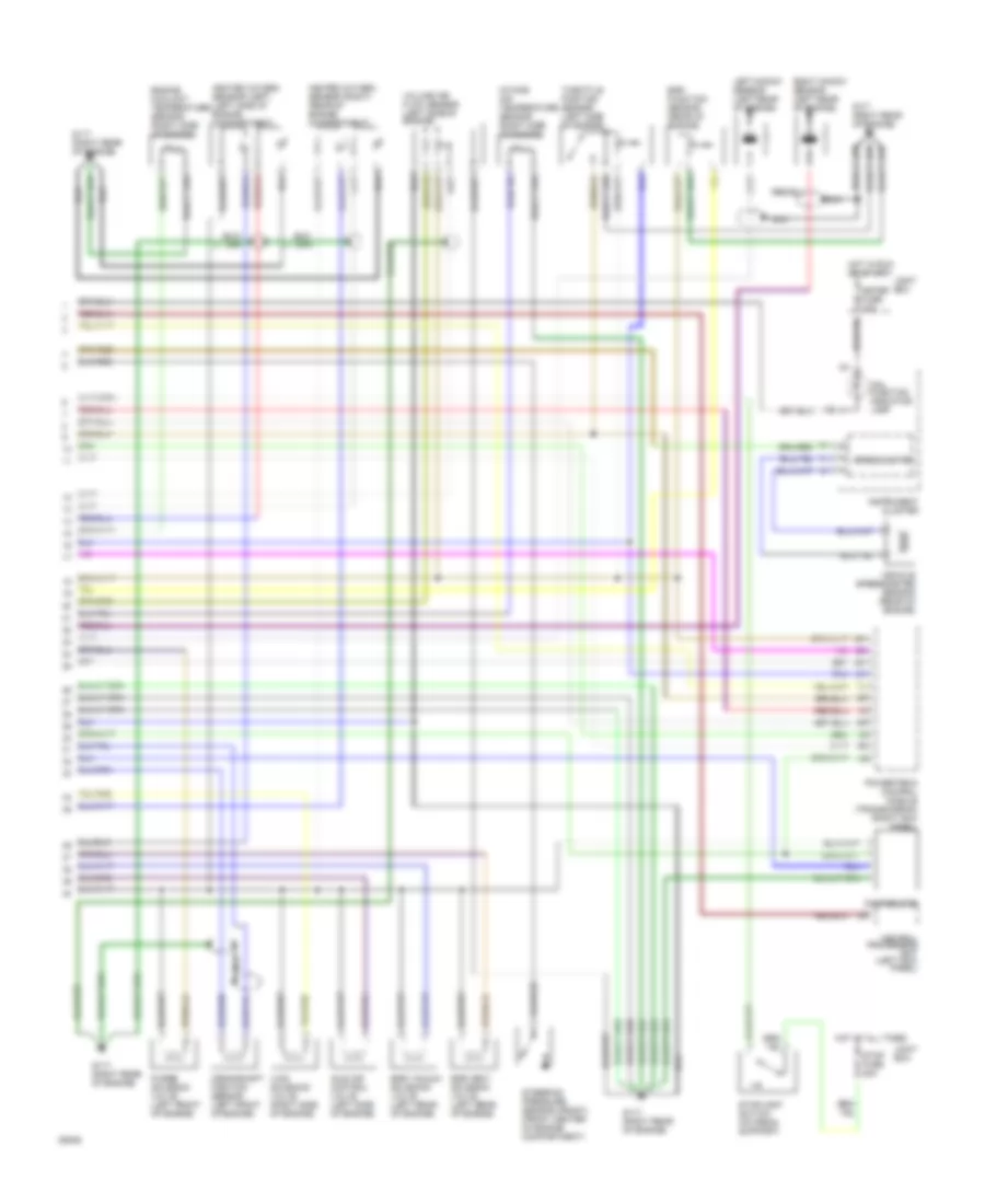
3.0L, Engine Performance Wiring Diagrams (1 of 2) for Mazda 929 1994

List of elements for 3.0L, Engine Performance Wiring Diagrams (1 of 2) for Mazda 929 1994:
- (at right kick panel)
- (below console)
- A/c amplifier
- A/c relay
- Acc
- Cold start injector (right rear of engine)
- Cold start thermo switch (right side of engine)
- Condenser (left side of engine compartment)
- Data link connector (left side of engine compartment)
- Diagnostic module
- Egi fuse 30a
- Egi main relay (left front of engine compartment)
- Engine fuse 10a
- Fuel injectors
- Fuel pump
- Fuel pump relay (in relay and fuse box)
- Fuel tank unit (in fuel tank)
- G100 (left front of engine compartment)
- G101 (right side of engine compartment)
- G302
- Hot at all times
- Hot in run or start
- Hot with engine cranking
- Igniter (left side of engine compartment)
- Ignition coil (left front of engine)
- Ignition switch
- Instrument cluster (tach)
- Joint box
- Main fuse box
- Main relay (in relay and fuse box)
- Off
- Pnk
- Powertrain control module (engine)
- Refrigerant pressure switch
- Relay and fuse box
- Room fuse 15a
- Run
- St sig fuse 10a
- Start
3.0L, Engine Performance Wiring Diagrams (2 of 2) for Mazda 929 1994
List of elements for 3.0L, Engine Performance Wiring Diagrams (2 of 2) for Mazda 929 1994:
- Central processing unit (left kick panel)
- Crankshaft position sensor (left front of engine)
- Distributor
- Egr function sensor (rear of engine)
- Egr vacuum solenoid valve (left rear of engine)
- Egr vent solenoid valve (left rear of engine)
- Engine coolant temperature sensor (right side of engine)
- G117 (right rear of engine)
- G117 (right rear of engine)
- Heated oxygen sensor (left) (left side of engine compartment)
- Heated oxygen sensor (right) (rear of engine compartment)
- Hot at all times
- Hot in run or start
- Idle air control valve (left side of engine)
- Instrument cluster
- Intake air temperature sensor (right side of engine)
- Joint box
- Left knock sensor (left rear of engine)
- Mal- function indicator lamp
- Meter fuse 10a
- Nca
- Powertrain control module (transmission) (right kick panel)
- Purge solenoid valve (left front of engine)
- Right knock sensor (left rear of engine)
- Speedometer
- Steering pressure sensor (front) (front center of engine compartment)
- Stop fuse 20a
- Stoplight switch (on pedal support)
- Throttle position sensor (left side of engine)
- Vehicle speedometer sensor (rear of engine)
- Vics solenoid valve (right side of engine)
- Volume air flow sensor (left side of engine)