POWER DOOR LOCKS
Power Door Lock Wiring Diagram, with Keyless Entry for Mazda 929 1994

List of elements for Power Door Lock Wiring Diagram, with Keyless Entry for Mazda 929 1994:
- C 1995 vftc
- Central processing unit (cpu)
- Door & trunk opener relay (behind left side of i/p)
- Door lock fuse 30a
- Door lock timer unit (behind left side of i/p)
- G121 (center of safety wall)
- G201 (right side of i/p)
- G203 (right kick panel)
- Hot at all times
- J/c 10
- J/c 3
- J/c 5
- Jb-11
- Joint box (left side of i/p)
- Joint box (left side of i/p)
- Keyless unit (rear shelf)
- Left front door key cylinder switch (unlock:on)
- Left front door lock switch
- Left front power door lock actuator
- Left rear power door lock actuator
- Lock
- Nca
- Pnk
- Relay
- Relay & fuse box (right side of engine compartment)
- Right front door key cylinder switch
- Right front power door lock actuator
- Right rear power door lock actuator
- Room fuse 12 15a
- Trunk & fuel door release system
- Trunk lid cancel switch
- Trunk lid opener
- Un- lock
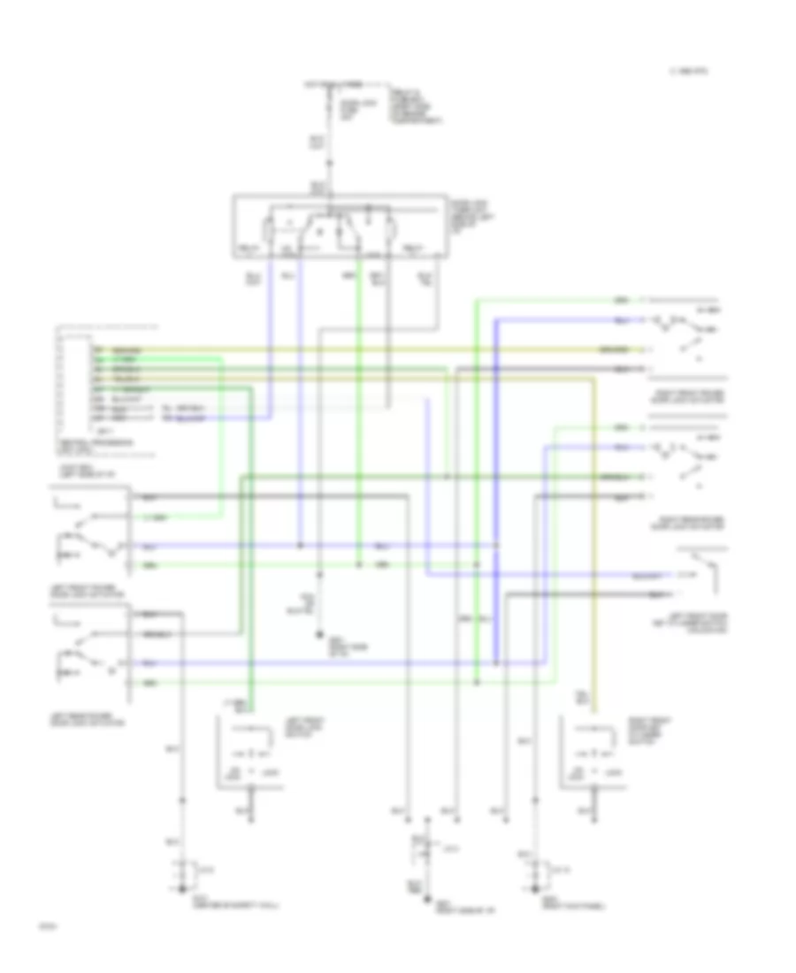
Power Door Lock Wiring Diagram, without Keyless Entry for Mazda 929 1994
List of elements for Power Door Lock Wiring Diagram, without Keyless Entry for Mazda 929 1994:
- C 1995 vftc
- Central processing unit (cpu)
- Door lock fuse 30a
- Door lock timer unit (behind left side of i/p)
- G121 (center of safety wall)
- G201 (right side of i/p)
- G203 (right kick panel)
- Hot at all times
- J/c 10
- J/c 3
- J/c 5
- Jb-11
- Joint box (left side of i/p)
- Left front door key cylinder switch (unlock:on)
- Left front door lock switch
- Left front power door lock actuator
- Left rear power door lock actuator
- Lock
- Nca
- Relay
- Relay & fuse box (right side of engine compartment)
- Right front door key cylinder switch
- Right front power door lock actuator
- Right rear power door lock actuator
- Un- lock