ENGINE PERFORMANCE
3.5L
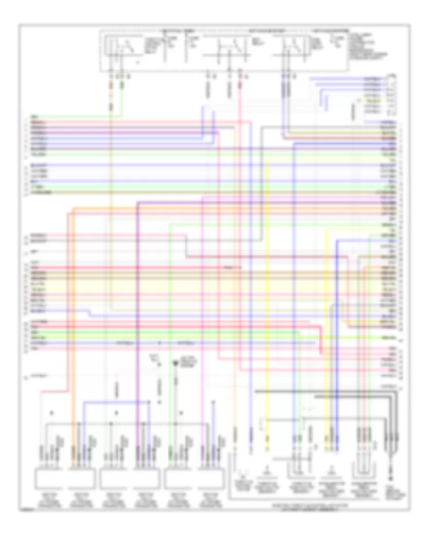
3.5L, Engine Performance Wiring Diagram (1 of 4) for Nissan 350Z 2006

List of elements for 3.5L, Engine Performance Wiring Diagram (1 of 4) for Nissan 350Z 2006:
- (behind right side of dash) f152
- (left front of engine) exhaust valve timing control magnet retarder (bank 2)
- (on top front of engine) f23
- (right front of engine) exhaust valve timing control magnet retarder (bank 1)
- 15a
- A/f-ip1
- Af-h1
- Af-h2
- Af-un1
- Af-vm1
- Avcc
- Avcc2
- C-evc(l)
- C-evc(r)
- C-ivc (l)
- C-ivc (r)
- Combination meter
- Condenser (top right rear of engine)
- Crankshaft position sensor (pos) (at left rear of engine, mounted on bottom of bell housing)
- Engine control module (right end of dash)
- Evap
- Evap canister purge volume control solenoid valve (on right side of intake manifold collector)
- Evcpus er
- Exhaust valve timing control position sensor (bank 1) (right rear of engine)
- F152 (behind right side of dash)
- Ftrps
- Fuel injector
- Fuse 10a
- Fuse block (j/b) (behind left kick panel)
- Gnd
- Hot in on or start
- Inj 1
- Inj 2
- Inj 3
- Inj 4
- Inj 5
- Inj 6
- Knk1
- Knock sensor (top center of engine)
- Malfunction indicator lamp
- Motor1
- Motor2
- Nca
- Neutral
- O2hrl
- O2hrr
- O2srl
- Park/ neutral position switch (integral to a/t device)
- Pdpres
- Phase lh
- Phase rh
- Pnk
- Pos
- Ps pres
- Qa+
- Red
- Refrigerant pressure sensor (on a/c liquid tank)
- Tps1
- Unified meter control unit
- V mot
3.5L, Engine Performance Wiring Diagram (2 of 4) for Nissan 350Z 2006
List of elements for 3.5L, Engine Performance Wiring Diagram (2 of 4) for Nissan 350Z 2006:
- (on top front of engine)
- Accelerator pedal position (app) sensor 1
- Accelerator pedal position (app) sensor 2
- E113
- Ecm relay
- Electric throttle control actuator (on throttle body assembly)
- F152 (behind right side of dash)
- F23
- F31
- Fuel pump relay
- Fuse 15a
- Hot at all times
- Hot in on or start
- Ignition coil 1 (w/ power transistor)
- Ignition coil 2 (w/ power transistor)
- Ignition coil 3 (w/ power transistor)
- Ignition coil 4 (w/ power transistor)
- Ignition coil 5 (w/ power transistor)
- Ignition coil 6 (w/ power transistor)
- Intelligent power distribution module engine room (right rear corner of engine compt)
- J/c
- Nca
- Nca nca
- Plug spark
- Pnk
- Spark plug
- Throttle control motor
- Throttle control motor relay
- Throttle position (tp) sensor 1
- Throttle position (tp) sensor 2
3.5L, Engine Performance Wiring Diagram (3 of 4) for Nissan 350Z 2006
List of elements for 3.5L, Engine Performance Wiring Diagram (3 of 4) for Nissan 350Z 2006:
- Air fuel ratio (a/f) sensor 1 (bank 1) (on right exhaust manifold, ahead of three way catalyst 1)
- Air fuel ratio (a/f) sensor 1 (bank 2) (on left exhaust manifold, ahead of three way catalyst 1)
- Camshaft position sensor (phase) (bank 1) (right rear of engine)
- Camshaft position sensor (phase) (bank 2) (left rear of engine)
- Engine coolant temperature sensor (on top right rear of engine)
- Evap control system pressure sensor (under vehicle, near evap canister)
- F152 (behind right side of dash)
- Fuse 15a
- Fuse block (j/b) (behind left kick panel)
- Heated oxygen sensor 2 (bank 1) (on right side exhaust pipe, between three way catalysts 1 and 2)
- Heated oxygen sensor 2 (bank 2) (on left side exhaust pipe, between three way catalysts 1 and 2)
- Hot in on or start
- Intake valve timing control solenoid valve (bank 1) (on right front of engine)
- Intake valve timing control solenoid valve (bank 2) (on left front of engine)
- J/c
- Mass airflow (maf) sensor (on intake air duct housing)
- Pnk
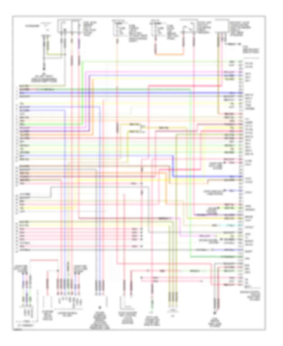
3.5L, Engine Performance Wiring Diagram (4 of 4) for Nissan 350Z 2006
List of elements for 3.5L, Engine Performance Wiring Diagram (4 of 4) for Nissan 350Z 2006:
- A/f ia1
- A/f-ia2
- A/f-ip2
- A/t assembly
- Af-un2
- Af-vm2
- Aps1
- Aps2
- Ascdsw
- At-p
- Avcc
- Avcc2
- Avvc
- B5 (on left front side of passenger's compartment floor)
- Batt
- Bncsw
- Brake
- Can l
- Can-h
- Can-l
- Cdcv
- Computer data lines system
- Condenser
- Cruise control system
- Data link connector (lower left side of dash)
- Ecm
- Engine control module (right end of dash)
- Evap canister vent control valve (on evap canister)
- Exhaust valve timing control position sensor (bank 2) (left rear of engine)
- F152 (behind right side of dash)
- Fpr
- Fuel level sensor unit & fuel pump (in fuel tank)
- Fuel sen
- Fuse 10a
- Fuse 15a
- Fuse block (j/b) (behind left kick panel)
- Fuse, fusible link & relay box (at right rear side of engine compt)
- Gnd
- Gnd 02
- Gnd a
- Gnd a2
- Hot at all times
- Ign 1
- Ign 2
- Ign 3
- Ign 4
- Ign 5
- Ign 6
- Ign sw
- J/c
- Kline
- Motrly
- O2srr
- Pdpres
- Pnk
- Power steering pressure sensor (on power steering high pressure tube)
- Red
- Ssoff
- Starter relay (on ipd module)
- Stop lamp switch (on brake pedal bracket)
- Str rly
- Tcm
- Tps2
- Unified meter & a/c amp
- Vmot