STARTING/CHARGING
Charging Wiring Diagram for Mitsubishi Raider LS 2008

List of elements for Charging Wiring Diagram for Mitsubishi Raider LS 2008:
- A803
- A919
- B(+)
- Battery
- Can c bus(+)
- Can c bus(-)
- Computer data lines system
- D64
- D65
- Front control module
- Fuse 20a
- Fused b(+)
- G105 (on left front of engine)
- G106 (at left side of engine compt)
- Gen field
- Gen sense
- Generator
- Integrated power module (at left side of engine compt)
- Ipm
- K20
- Powertrain control module (at right side of engine compt)
- Red
- S129
- S133
- Starter
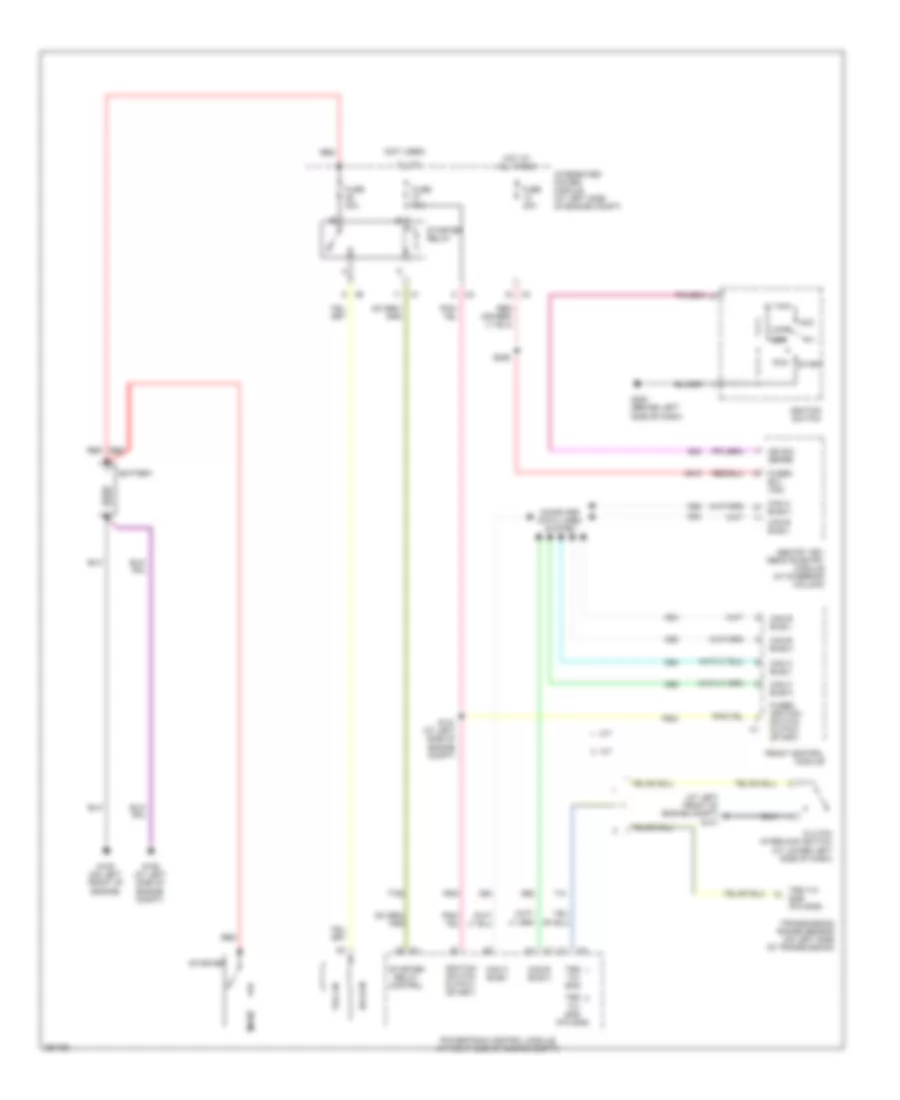
Starting Wiring Diagram for Mitsubishi Raider LS 2008
List of elements for Starting Wiring Diagram for Mitsubishi Raider LS 2008:
- (at left front of engine compt) g101
- (not used)
- A/t
- A918
- Acc
- Battery
- Can b bus(+)
- Can b bus(-)
- Can c bus(+)
- Can c bus(-)
- Clutch interlock switch (at lower left side of dash)
- Computer data lines system
- D54
- D55
- D64
- D65
- F924
- Front control module
- Fuse 10a
- Fuse 20a
- Fuse 30a
- Fused b(+) (iod)
- Fused ignition switch output (start)
- G105 (on left front of engine)
- G106 (at left side of engine compt)
- G20
- G200 (behind left side of dash)
- Hold-in
- Hot at all times
- Ign sw sense
- Ignition switch
- Ignition switch output (start)
- Integrated power module (at left side of engine compt)
- Lock
- M/t
- Off
- Powertrain control module (at right side of engine compt)
- Pull-in
- Red
- Run
- S131 (at left side of engine compt)
- S206
- Sentry key remote entry module (at steering column)
- Start
- Starter
- Starter relay
- Starter relay control
- T41
- T752
- Transmission range sensor (on left side of transmission)
- Trs t41 sns
- Trs t41 sns (p/n sns)