AIR CONDITIONING
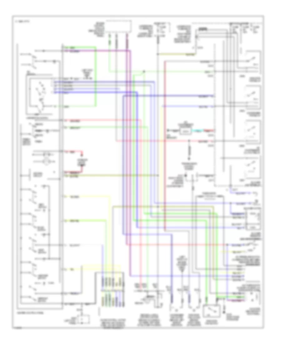
Heater Wiring Diagram for Acura Integra GS 1999

List of elements for Heater Wiring Diagram for Acura Integra GS 1999:
- (behind glove box on rear left side of blower housing)
- (behind glove box, on top of blower motor housing)
- (left kick
- (left kick panel) g200
- All times
- Bi-lev switch
- Blower motor (behind glove box, on bottom of blower motor housing)
- Blower motor relay
- Blower resistor
- C 1995 vftc
- C216
- C217
- C439
- C907
- Compartment)
- Defrost switch
- Dimming circuit
- Fresh
- Fresh/ recirc switch
- Fuse 40a
- Fuse 7.5a
- G101 (right front corner of engine
- G200
- Heat switch
- Heat/def switch
- Heater control panel
- Heater fan switch
- Hot at
- Hot in on
- Interior lights system
- Mode control motor (behind left side of dash, on left side of heater assembly)
- Off
- Panel)
- Recirc
- Recirculation control motor
- Red
- Underdash fuse/relay box (under left side of dash)
- Underhood fuse/relay box (right rear corner of engine compt, near battery)
- Vent switch
Manual A/C Wiring Diagram for Acura Integra GS 1999
List of elements for Manual A/C Wiring Diagram for Acura Integra GS 1999:
- (behind glove box)
- (behind glove box, on rear left side of blower housing)
- (left front of engine compart- ment) g100
- (left kick
- (left kick panel) g200
- (on bracket)
- A/c compressor clutch
- A/c compressor clutch relay
- A/c diode (above right kick panel)
- A/c pressure switch (in refrig pipe, between receiver-driver & condenser)
- A/c switch
- A/c thermostat (in evap housing, on evaporator core)
- Bi-lev switch
- Blower motor
- Blower motor relay
- Blower resistor
- C 1995 vftc
- C215
- C216
- C217
- C439
- C904
- C905
- C906
- C907
- Compartment)
- Condenser fan motor (behind left side of radiator)
- Condenser fan relay
- Defrost switch
- Dimming circuit
- Diode
- Engine control module (behind right side kick panel)
- Fresh
- Fresh/ recirc switch
- Fuse 20a
- Fuse 40a
- Fuse 7.5a
- G101 (right front corner of engine
- G120 (right side of engine)
- G200
- Heat switch
- Heat/def switch
- Heater control panel
- Heater fan switch
- High
- Hot at all times
- Hot in on underdash fuse/relay box (under left side of dash)
- Interior lights system
- Low
- Mode control motor (behind left side of dash, on left side of heater assembly)
- Nca
- Off
- Panel)
- Radiator fan motor (behind right side of radiator)
- Radiator fan relay
- Radiator fan switch
- Recirc
- Recirculation control motor
- Red
- Thermistor
- Transmission control system
- Underhood fuse/relay box (right rear corner of engine compt, near battery)
- Vent switch