ENGINE PERFORMANCE
1.8L
1.8L, Engine Performance Wiring Diagram (1 of 2) for Acura Integra GS 1999

List of elements for 1.8L, Engine Performance Wiring Diagram (1 of 2) for Acura Integra GS 1999:
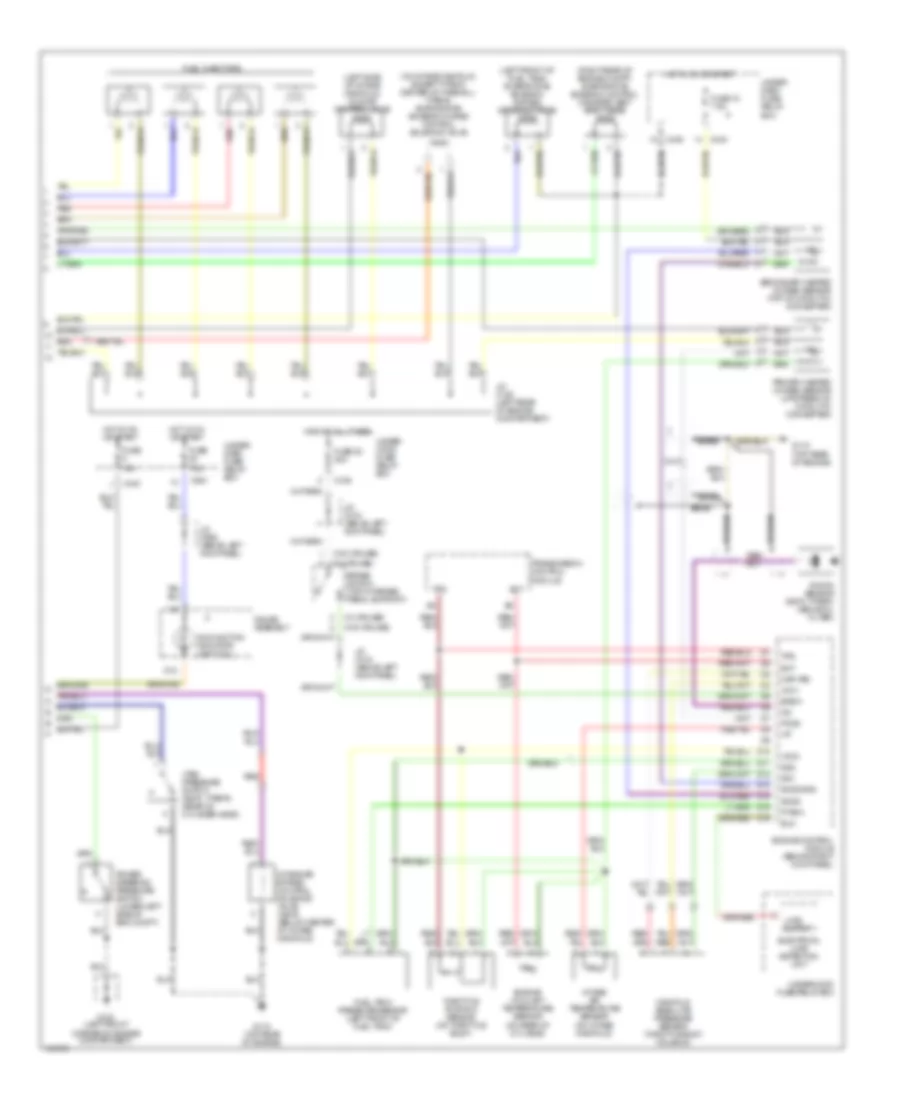
1.8L, Engine Performance Wiring Diagram (2 of 2) for Acura Integra GS 1999
List of elements for 1.8L, Engine Performance Wiring Diagram (2 of 2) for Acura Integra GS 1999: