AIR CONDITIONING
Automatic A/C Wiring Diagram (1 of 2) for Mercedes-Benz CLS550 2011

List of elements for Automatic A/C Wiring Diagram (1 of 2) for Mercedes-Benz CLS550 2011:
- (right front footwell) w15/1
- 12v
- Ac compressor (lower left front of engine)
- Activated charcoal filter flap adjustment motor
- Blower motor
- Blower regulator
- C77
- Can-b h
- Can-b l
- Comfort aac pushbutton control module
- Computer data lines system
- Df sig
- Driver-side sam control module w/ fuse & relay module (left side of engine compt)
- Evaporator temperature sensor (left side of hvac unit)
- Fresh air/ recirculated air flap actuator motor (on hvac unit)
- Front prefuse box (right front footwell)
- Fuse 25a
- Fuse 40a
- Fuse 7.5a
- Heating systems recirculation unit
- Hot at all times
- Hot w/ engine circuit 87 relay energized
- Left blending air flap actuator
- Left center air outlet flap actuator motor (on hvac unit)
- Left defroster vent flap actuator motor (on hvac unit)
- Left footwell flap positioning motor (on hvac unit)
- Left rear air blending air flap actuator motor (on hvac unit)
- Nca
- Rear window defroster switch
- Recirculated air switch
- Refrigerant pressure sensor (left front of engine compt)
- Right blending air flap actuator
- Right center air outlet flap actuator motor (on hvac unit)
- Right defroster vent flap actuator motor (on hvac unit)
- Right footwell flap positioning motor (on hvac unit)
- Right rear air blending air flap actuator motor (on hvac unit)
- W15/1 (right front footwell)
- Window defrost switch
- X26-1
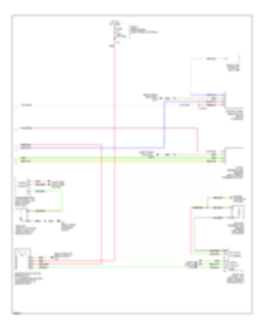
Automatic A/C Wiring Diagram (2 of 2) for Mercedes-Benz CLS550 2011
List of elements for Automatic A/C Wiring Diagram (2 of 2) for Mercedes-Benz CLS550 2011:
- (right front footwell) w15/1
- (right front of engine compt)
- C71
- Can-b h
- Can-b l
- Can-c h
- Can-c l
- Circuit 58d potential splitter
- Computer data lines system
- Control panel rear switch group (4 zone ac)
- Coolant circulation pump (right front of engine compt)
- Coolant temperature sensor (left rear of engine)
- E a tmoti
- Egs
- Electric suction fan engine & ac w/ integrated control (center front of engine compt)
- Engine controls system
- Front prefuse box (right front footwell)
- Fuse 100a (or 150a)
- Hot at all times
- In-car temperature sensor (right side of steering column)
- M r senm2
- Me-sfi (me) control unit (right rear of engine compt)
- Passenger side sam control unit (right front footwell)
- Red
- W2 (right front of engine compt)
- X18/35-1