SUPPLEMENTAL RESTRAINTS
Emergency Seat Belt Tensioners Wiring Diagram for Mercedes-Benz CLS550 2011

List of elements for Emergency Seat Belt Tensioners Wiring Diagram for Mercedes-Benz CLS550 2011:
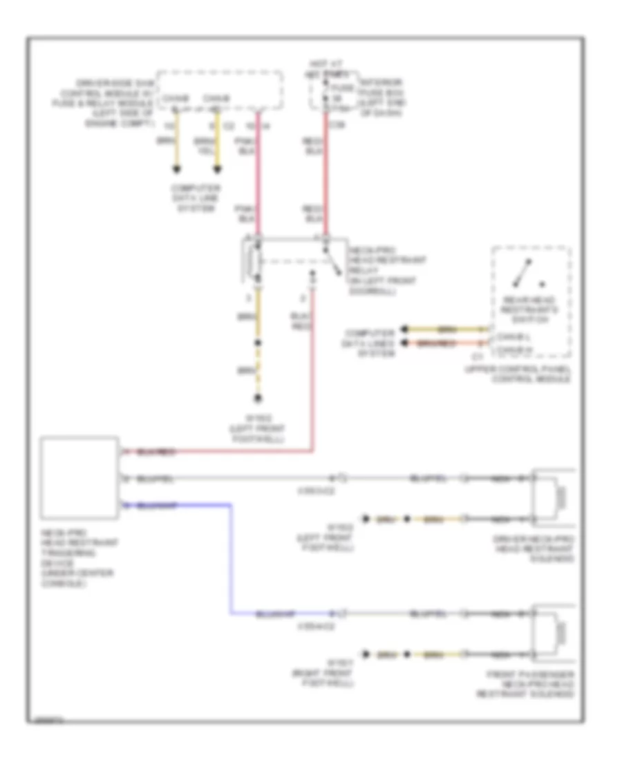
NECK-PRO Head Restraints Wiring Diagram for Mercedes-Benz CLS550 2011
List of elements for NECK-PRO Head Restraints Wiring Diagram for Mercedes-Benz CLS550 2011:
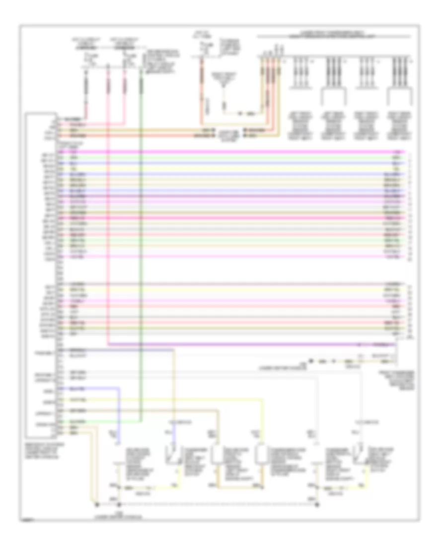
Supplemental Restraint Wiring Diagram (1 of 2) for Mercedes-Benz CLS550 2011
List of elements for Supplemental Restraint Wiring Diagram (1 of 2) for Mercedes-Benz CLS550 2011:
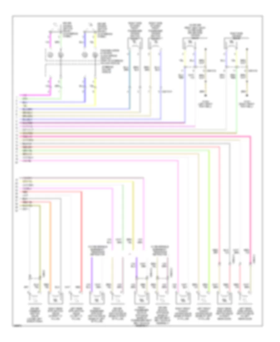
Supplemental Restraint Wiring Diagram (2 of 2) for Mercedes-Benz CLS550 2011
List of elements for Supplemental Restraint Wiring Diagram (2 of 2) for Mercedes-Benz CLS550 2011:
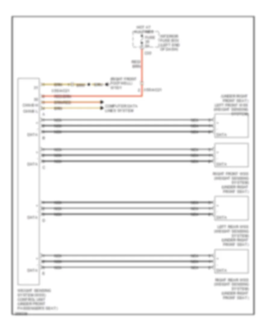
Weight Sensing System Wiring Diagram for Mercedes-Benz CLS550 2011
List of elements for Weight Sensing System Wiring Diagram for Mercedes-Benz CLS550 2011: