AIR CONDITIONING
Air Conditioning Wiring Diagrams (1 of 2) for Mercedes-Benz E320 1995

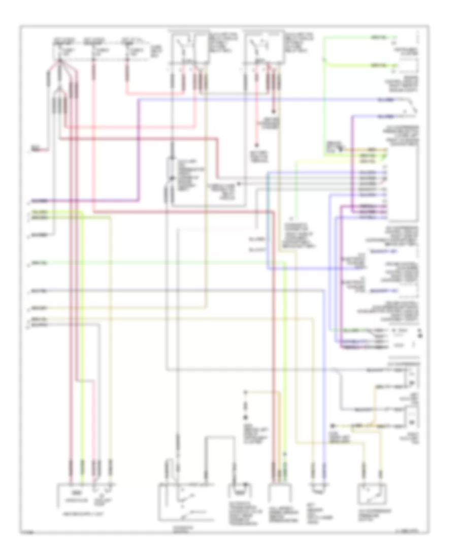
List of elements for Air Conditioning Wiring Diagrams (1 of 2) for Mercedes-Benz E320 1995:
- (behind left
- (right side of steering column)
- A/c pushbutton control unit
- Acc
- Blower motor
- C 1995 vftc
- Center outlet flap
- Climate control auxiliary fuse 30a (left side of component compartment)
- Cluster)
- Defrost flap long stroke
- Defrost flap short stroke
- Diverter flap
- Electronic blower control (rear of engine compartment)
- Evaporator temperature sensor
- Fresh/ recirc flap long stroke
- Fresh/ recirc flap short stroke
- Fresh/recirculated air switch
- G202
- G202 (behind left side of instrument cluster)
- Heater core temperature sensor (below radio)
- Hot at all times
- Ignition switch
- In-car temperature sensor (part of dome lamp)
- In-car temperature sensor aspirator (top of passenger's footwell)
- Instrument
- Interior lights system
- Legroom flap
- Nca
- Off
- Outside temperature sensor (right side of component compartment)
- Run
- Side of
- Start
- Switch- over valve unit (above passenger's footwell area)
- Test connector (left of battery)
Air Conditioning Wiring Diagrams (2 of 2) for Mercedes-Benz E320 1995
List of elements for Air Conditioning Wiring Diagrams (2 of 2) for Mercedes-Benz E320 1995:
- (behind battery) g105
- (right side of
- 15a
- 30a
- A/c compressor
- A/c compressor control module (right side of component compartment, behind battery)
- A/c compressor pressure switch
- A/c compressor pressure switch (lower left front of engine compartment)
- Automatic transmission kickdown valve (right rear corner of transmission)
- Auxiliary fan preresistor (front corner of engine compart- ment)
- Auxiliary fan relay module (stage 1) (in fuse/ relay box)
- Auxiliary fan relay module (stage 2) (in fuse/ relay box)
- Battery positive terminal
- Behind battery)
- C 1995 vftc
- Compartment,
- Component
- Coolant pump
- Cruise control/ idle speed control module (right side of component compt)
- Cruise control/ idle speed/electronic accelerator control module (right side of component compt)
- Diagnostic connector
- Ect
- Engine control module (right rear of engine compt)
- Fuse 5 8a
- Fuse 7 16a
- Fuse d 16a
- Fuse/ relay box
- G106 (near left headlamp)
- G202 (behind left side of instrument cluster)
- Hall effect speed sensor (behind speedometer)
- Heated
- Hot at all times
- Hot in run or start
- Instrument cluster
- Kickdown switch
- Left auxiliary fan
- Monovalve
- Nca
- Overvoltage protection relay module
- Red
- Right auxiliary fan
- Sensor (a/c) (on cylinder head)
- W/ electronic acceler- ator
- W/o electronic acceler- ator
- Windshield washer