ENGINE PERFORMANCE
3.2L
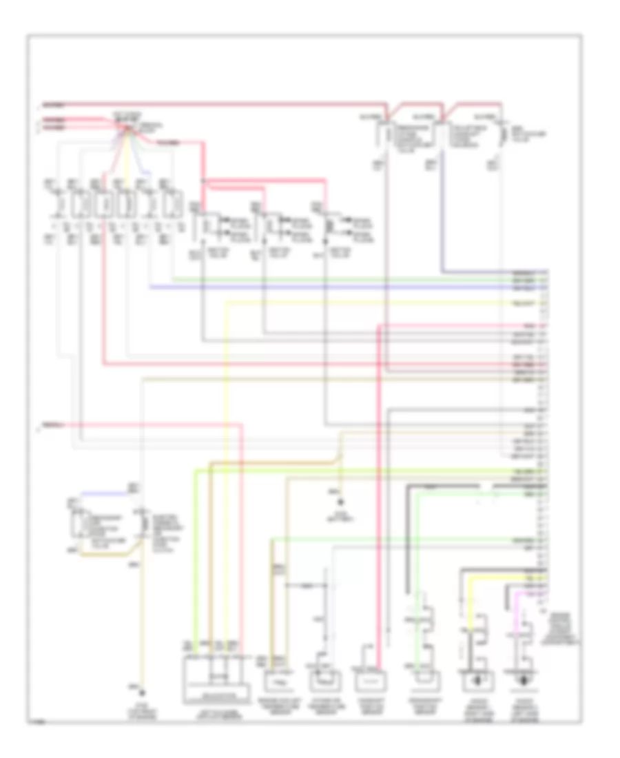
3.2L, Engine Performance Wiring Diagrams (1 of 2) for Mercedes-Benz E320 1995

List of elements for 3.2L, Engine Performance Wiring Diagrams (1 of 2) for Mercedes-Benz E320 1995:
- (center console)
- (in right component compt.)
- 15a
- 15u
- 30z
- 30a
- 40a
- 87e
- 87m
- 87u
- A/c comp. control module
- Acc
- Auxiliary fan relay module
- Battery
- Canada
- Cc/isc control module
- Computer data lines
- Data link connector (dtc readout) (in right component compt.)
- Ea/cc/isc control module
- Electronic clock/ tachometer
- Engine control module (hfm-sfi) (in right component compt.)
- Fuel pump
- Fuel pump relay module
- Fuse & relay box
- Fuse 16a
- Fuse 8a
- G105 (battery)
- G302
- Hot at all times
- Hot in run or start
- Ignition switch
- Lock
- Nca
- O2s 1 (before
- Overvoltage protection relay module (in right component compt.)
- P/n
- Pnk/ red
- Pnk/red
- Purge control valve
- Red
- Run
- Solid state
- Start
- Starter
- Starter lock- out relay module
- Starter lock-out/ backup lamp switch
- Terminal block
- Transmission overload protection switch
- Twc)
- U.s.
- Upshift delay switch- over valve
- W/ ea
- W/o ea
3.2L, Engine Performance Wiring Diagrams (2 of 2) for Mercedes-Benz E320 1995
List of elements for 3.2L, Engine Performance Wiring Diagrams (2 of 2) for Mercedes-Benz E320 1995:
- (left side
- (right side
- Adjustable camshaft timing solenoid
- Camshaft position sensor
- Crankshaft position sensor
- Egr switchover valve
- Electro- magnetic secondary air injection pump clutch
- Engine control module (in right component compartment)
- Engine coolant temperature sensor
- G105 (battery)
- G125 (top front of engine)
- Hot film mass air flow sensor
- Hot in run or start
- Ignition coil #1
- Ignition coil #2
- Ignition coil #3
- Inj. #1
- Inj. #2
- Inj. #3
- Inj. #4
- Inj. #5
- Inj. #6
- Intake air temperature sensor
- Knock
- Nca
- Of engine)
- Pnk
- Pnk/ red
- Pnk/red
- Resonance intake manifold switchover valve
- Secondary air injection pump switchover valve
- Sensor 1
- Sensor 2
- Solid state
- Spark plug #1
- Spark plug #2
- Spark plug #3
- Spark plug #4
- Spark plug #5
- Spark plug #6
- Terminal block