AIR CONDITIONING
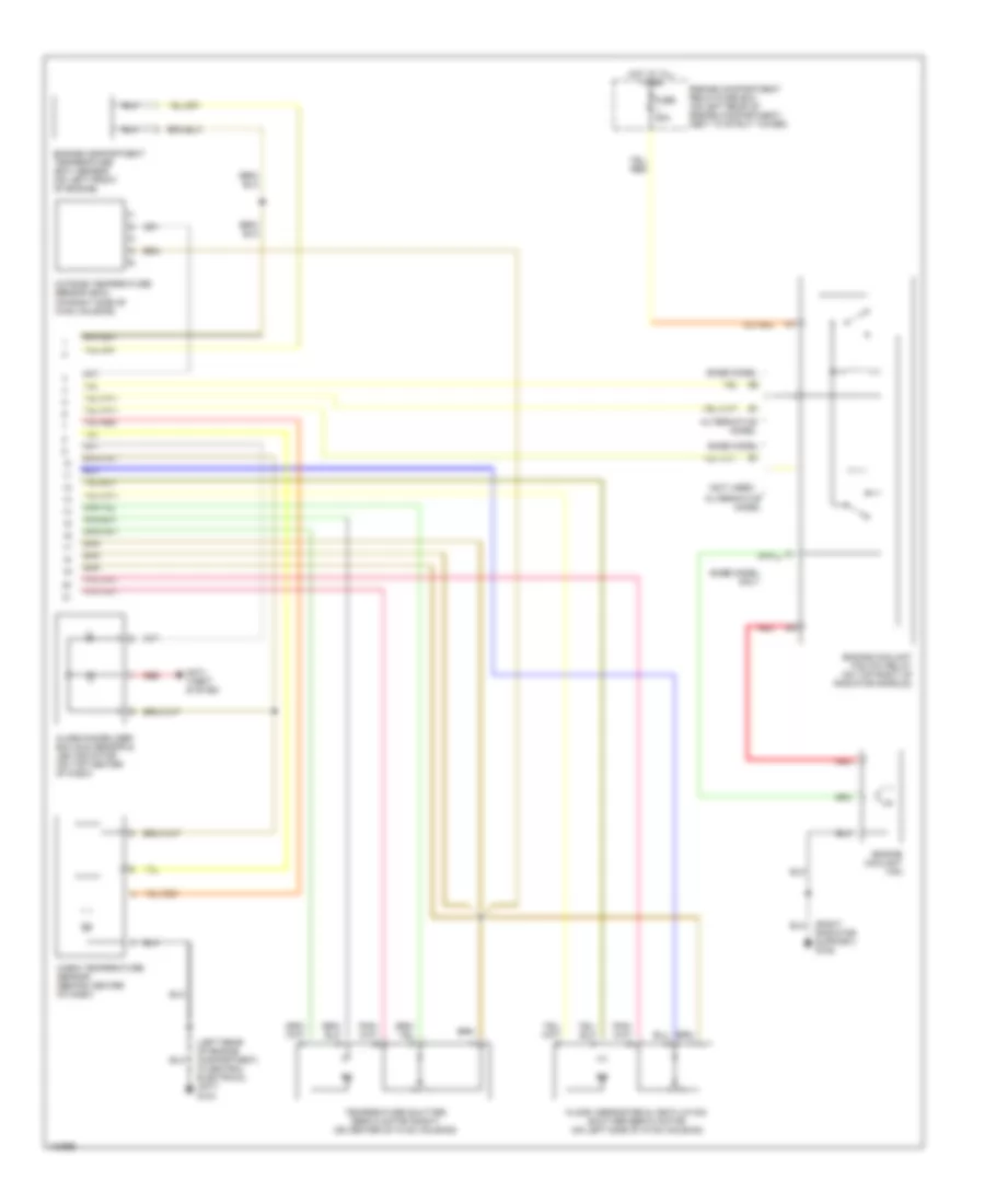
A/C Wiring Diagram, Auto A/C (1 of 2) for Volvo V70 1998

List of elements for A/C Wiring Diagram, Auto A/C (1 of 2) for Volvo V70 1998:
- (on center console, rear of of shift lever)
- (rear of right front fender) g105
- 2.3l & 2.4l turbo
- 2.4l engine
- 87a
- A/c pressure sensor (on right front of engine compartment)
- A/c pressure switch (pressostat) (on right rear of engine compartment)
- A/c relay (on engine compartment relay/fuse box, position no 4)
- A/c switch solenoid (on a/c compressor)
- A10
- A11
- A12
- A13
- A14
- A15
- A16
- A17
- A18
- A19
- A20
- A21
- A22
- A23
- A24
- A25
- A26
- A27
- A28
- A29
- A30
- A31
- B23
- B25
- B28
- B29
- B40
- Base model
- Blower fan (behind right side of dash, on hvac housing)
- Blower fan power unit (on right side of hvac housing)
- C10
- Central electrical unit (on left rear of engine compartment)
- Data link connector (dlc)
- Ecc climate control module
- Engine compartment relay/fuse box (on left rear of engine compartment, next to strut tower)
- Engine control module (ecm) (on right front inner fender panel, in control module box)
- Fuse 10a
- Fuse 15a
- Fuse 25a
- Hot at all times
- Hot in acc or on
- Hot in on or start
- Illum
- Instrument cluster system
- Nca
- Pnk
- Recirculation shutter servo motor (on right side of hvac housing)
- Red
- Rheostat
- Starting/ charging system (generator)
- Temperature shutter servo motor (left) (on left side of hvac housing)
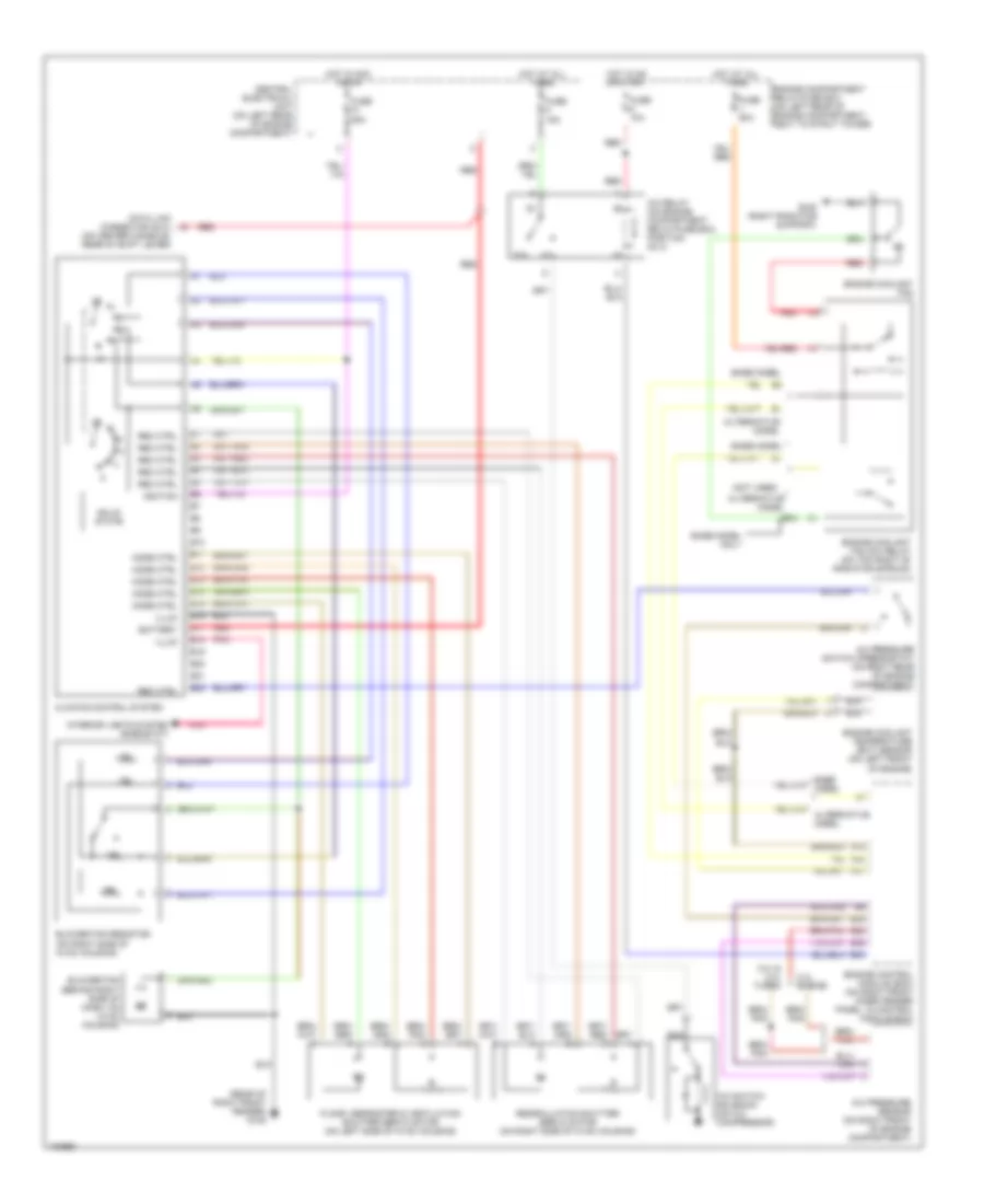
A/C Wiring Diagram, Auto A/C (2 of 2) for Volvo V70 1998
List of elements for A/C Wiring Diagram, Auto A/C (2 of 2) for Volvo V70 1998:
- (left rear of engine compartment, in central electrical unit) g104
- (not used)
- (right radiator support) g109
- Alarm/immobilizer ecc sun sensor & led indicator (on top center of dash)
- Alternative model
- Anti- theft system
- Base model
- Base model only
- Cabin temperature sensor (behind center of dash)
- Engine compartment relay/fuse box (on left rear of engine compartment, next to strut tower)
- Engine compartment temperature (ect) sensor (on left front of engine)
- Engine coolant fan
- Engine coolant fan (fc) relay (on top right of radiator shroud)
- Floor, defroster & ventilation shutter servo motor (on left side of hvac housing)
- Fuse 60a
- Hot at all times
- Outside temperature sensor (ecc) (on right side of hvac housing)
- Red
- Temperature shutter servo motor (right) (on center of hvac housing)
A/C Wiring Diagram, Manual A/C for Volvo V70 1998
List of elements for A/C Wiring Diagram, Manual A/C for Volvo V70 1998:
- (not used)
- (on center console, rear of shift lever)
- (rear of right front fender) g105
- 2.3l & 2.4l turbo
- 2.4l engine
- 87a
- A/c pressure sensor (on right front of engine compartment)
- A/c pressure switch (pressostat) (on right rear of engine compartment)
- A/c relay (on engine compartment relay/fuse box, position no 4)
- A/c switch solenoid (on a/c compressor)
- A18
- A22
- A31
- Alternative model
- B10
- B11
- B12
- B13
- B14
- B15
- B16
- B17
- B18
- B19
- B20
- B21
- B22
- B25
- B28
- B29
- B40
- Base model
- Base model only
- Battery
- Blower fan (behind right side of dash, on hvac housing)
- Blower fan resistor (on right side of hvac housing)
- Central electrical unit (on left rear of engine compartment)
- Climate control system
- Data link connector (dlc)
- Engine compartment relay/fuse box (on left rear of engine compartment, next to strut tower)
- Engine control module (ecm) (on right front inner fender panel, in control module box)
- Engine coolant fan
- Engine coolant fan (fc) relay (on top right of radiator shroud)
- Engine coolant temperature (ect) sensor (on left front of engine)
- Floor, defroster & ventilation shutter servo motor (on left side of hvac housing)
- Fuse 10a
- Fuse 15a
- Fuse 25a
- Fuse 60a
- G109 (right radiator support)
- Hot at all times
- Hot in acc or on
- Hot in on or start
- Ignition
- Illum
- Interior lights system (rheostat)
- Mode ctrl
- Nca
- Pnk
- Rec ctrl
- Recirculation shutter servo motor (on right side of hvac housing)
- Red
- Solid state
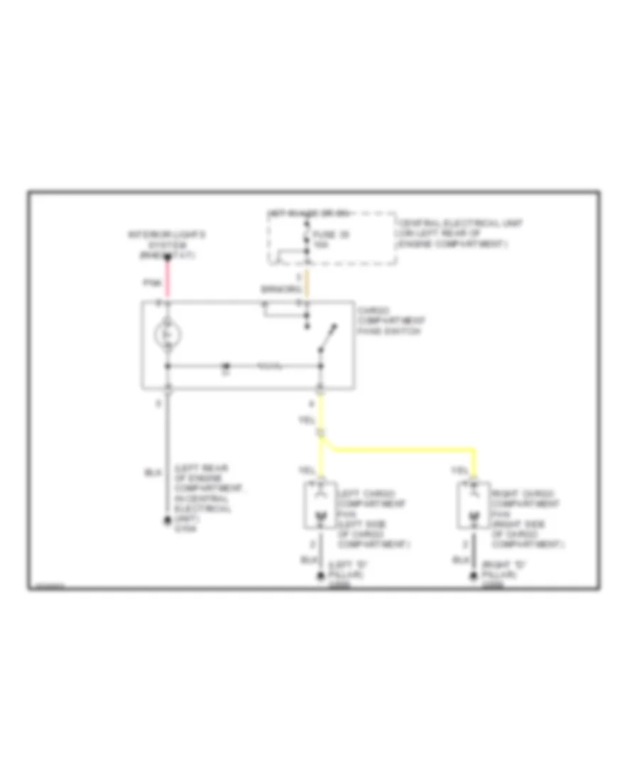
Cargo Compartment Fans for Volvo V70 1998
List of elements for Cargo Compartment Fans for Volvo V70 1998:
- (left "d" pillar) g999
- (left rear of engine compartment, in central electrical unit) g104
- (right "d" pillar) g998
- Cargo compartment fans switch
- Central electrical unit (on left rear of engine compartment)
- Fuse 35 10a
- Hot in acc or on
- Interior lights system (rheostat)
- Left cargo compartment fan (left side of cargo compartment)
- Pnk
- Right cargo compartment fan (right side of cargo compartment)