NAVIGATION
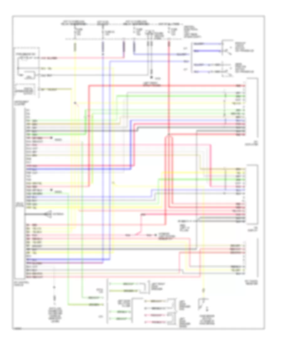
Navigation Wiring Diagram for Volvo V70 1998
List of elements for Navigation Wiring Diagram for Volvo V70 1998:
- (left front strut tower)
- A/t
- A10
- A11
- A12
- A13
- A14
- A15
- A16 a15
- A17
- A18
- A19
- A20
- A21
- A22
- A23
- A24
- A25
- A26
- A27
- A28
- A29
- A30
- Antenna
- B10
- B11
- B12
- B13
- B14
- B15
- B16
- Back-up lights switch (on transaxle)
- C70
- Central electrical unit (left rear of eng compt)
- Cpu
- Data link connector (on center console, near shift lever)
- Digital speedometer output
- Fuse c15 10a
- Fuse c2 10a
- Fuse c27 15a
- Fuse c30 15a
- G102
- G900 (left "a" pillar)
- Gear position switch (on transaxle)
- Hand brake switch (at base of hand brake)
- Hot at all times
- Hot in on or start
- Hot w/ overload relay 105 energized
- Hot w/ overload relay 106 energized
- Instrument cluster
- Interior light system (rheostat)
- Left door speaker (bass)
- Left door speaker (mid)
- Left door splitting filter
- Left front door speaker
- M/t
- Nca
- Park brake ind.
- Pnk
- Power ground conn.
- Radio
- Red
- Rti cd-player
- Rti control module
- Rti tmc/fm receiver
- S70 & v70
- Solid state
- Tri display
 English