ANTI-LOCK BRAKES
Anti-lock Brakes Wiring Diagram for Mercedes-Benz CLK500 2003
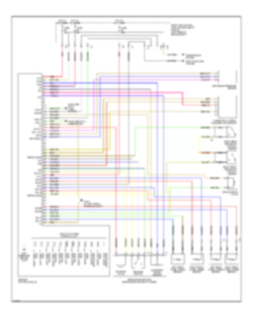
List of elements for Anti-lock Brakes Wiring Diagram for Mercedes-Benz CLK500 2003:
- +5v
- Ba mv+
- Ba mv-
- Bla
- Body computer system
- Brake booster (bas) (near brake master cylinder)
- Brake wear
- C10
- C13
- C26
- Can h
- Can l
- Computer data lines system
- Dg1 +15v
- Dg1-signal
- Dg1m
- Diag
- Diaphragm travel sensor
- Esp brake pressure sensor
- Esp/bas control module
- Front axle inlet
- Front axle switchover
- Front sam control module fuse & relay module (left rear of engine compt)
- Fuse 40a
- Fuse 50a
- Fuse 5a
- High- pressure return pump
- Hold left front
- Hot at all times
- Inlet rear axle
- Left front release
- Left front wheel speed sensor
- Left rear hold
- Left rear wheel speed sensor
- Ls1
- Ls2
- Lsr
- Mp-
- Mps
- Nca
- Rear axle switchover
- Red
- Release left rear
- Release right rear
- Release switch
- Right front brake pad contact sensor
- Right front hold
- Right front release
- Right front wheel speed sensor
- Right rear brake pad contact sensor
- Right rear hold
- Right rear wheel speed sensor
- Solenoid valve
- Sps solenoid valve
- Ss lf
- Ss lr
- Ss rf
- Ss rr
- Traction system hydraulic unit
- Transmission system
- Turnrate & lateral acceleration sensor
- Um 1
- Um 2
- Vss lf
- Vss rf
- W16/3 (at left front of engine compt)
 English