NAVIGATION
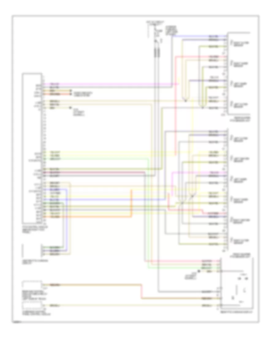
Parktronic Wiring Diagram, Convertible for Mercedes-Benz CLK500 2003

List of elements for Parktronic Wiring Diagram, Convertible for Mercedes-Benz CLK500 2003:
- (+) sf
- (+) sr
- (-) sf
- (-) sr
- 15r
- C10
- C12
- Can h
- Can l
- Center pts warning display
- Computer data lines system
- Front bumper pts sensor unit
- Fuse 5a
- Hot at circuit 15 relay 1
- Interior fuse box (left side of dash)
- Left center sensor
- Left inner sensor
- Left outer sensor
- N.c.
- Pts control module (behind right kick panel)
- Rear bumper pts sensor unit
- Rear pts warning display
- Right center sensor
- Right inner sensor
- Right outer sensor
- S1 f
- S10 r
- S2 f
- S3 f
- S4 f
- S5 f
- S6 f
- S7 r
- S8 r
- S9 r
- W f (+)
- W f (-)
- W f (data)
- W r (+)
- W r (-)
- W r (data)
- W19 (at right doorsill)
Parktronic Wiring Diagram, Except Convertible for Mercedes-Benz CLK500 2003
List of elements for Parktronic Wiring Diagram, Except Convertible for Mercedes-Benz CLK500 2003:
- (+) sf
- (+) sr
- (-) sf
- (-) sr
- 15r
- C10
- C12
- C17
- Can h
- Can l
- Center pts warning display
- Computer data lines system
- Front bumper pts sensor unit
- Fuse 5a
- Hot at circuit 15 relay 1
- Interior fuse box (left side of dash)
- Left center sensor
- Left inner sensor
- Left outer sensor
- N.c.
- Overhead control panel control module
- Pts control module (behind right kick panel)
- Rear bumper pts sensor unit
- Rear pts warning display
- Rear sam control module fuse & relay module (left side of trunk)
- Right center sensor
- Right inner sensor
- Right outer sensor
- S1 f
- S10 r
- S2 f
- S3 f
- S4 f
- S5 f
- S6 f
- S7 r
- S8 r
- S9 r
- W f (+)
- W f (-)
- W f (data)
- W r (+)
- W r (-)
- W r (data)
- W19 (at right doorsill)
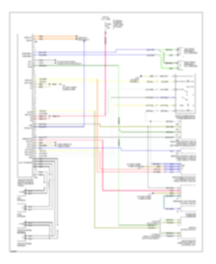
Tele Aid Wiring Diagram, with D2B Data Bus for Mercedes-Benz CLK500 2003
List of elements for Tele Aid Wiring Diagram, with D2B Data Bus for Mercedes-Benz CLK500 2003:
- (at right rear wheelhouse) w7
- 15r
- 58d
- Airbag sig
- Aux. antenna
- C11
- C21
- C23
- C25
- C26
- Can h
- Can l
- Computer data lines system
- Ctel antenna
- D2b
- D2b data bus circuit
- D2b in
- D2b out
- Diag
- Frequency switchover control module
- Front sam control module fuse & relay module (left rear of engine compt)
- Fuse 7.5a
- Gps
- Gps antenna
- Hot at all times
- Info led
- Info sw
- Interior fuse box (left side of dash)
- J10
- Led
- Left front emergency call speaker
- Mb-info & breakdown assistance switch
- Mic +
- Mic -
- Mute
- Navigation system (voice activation circuit)
- Nca
- Pnk
- Radio & navigation unit
- Radio/command operating, display & control unit
- Rap sw
- Rear sam control module fuse & relay module (left side of trunk)
- Rf sw
- Right front emergency call speaker
- Sos led
- Sos pushbutton switch (in overhead control panel control module)
- Sos sw
- Speaker +
- Speaker -
- Tele aid spare antenna
- Tele aid system control module (front center of trunk)
- Telephone interface
- Unlock
- W/ auto pilot circuit
- W/ radio circuit/ command actuation circuit
- W19 (at right doorsill)
- W7 (at right rear wheelhouse)
- Wake up
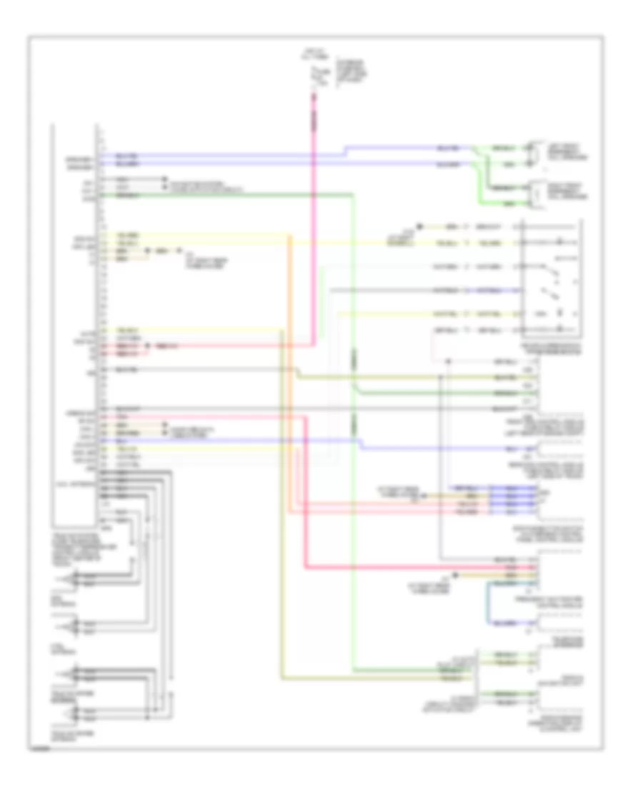
Tele Aid Wiring Diagram, without D2B Data Bus for Mercedes-Benz CLK500 2003
List of elements for Tele Aid Wiring Diagram, without D2B Data Bus for Mercedes-Benz CLK500 2003:
- (at right rear wheelhouse) w7
- 15r
- 58d
- Airbag sig
- Aux. antenna
- C11
- C21
- C23
- C25
- C26
- Can h
- Can l
- Computer data lines system
- Ctel antenna
- Diag
- Frequency switchover control module
- Front sam control module fuse & relay module (left rear of engine compt)
- Fuse 7.5a
- Gps
- Gps antenna
- Hot at all times
- Info led
- Info sw
- Interior fuse box (left side of dash)
- J10
- Led
- Left front emergency call speaker
- Mb-info & breakdown assistance switch
- Mic +
- Mic -
- Mute
- Navigation system (voice activation circuit)
- Nca
- Pnk
- Radio & navigation unit
- Radio/command operating, display & control unit
- Rap sw
- Rear sam control module fuse & relay module (left side of trunk)
- Rf sw
- Right front emergency call speaker
- Sos led
- Sos pushbutton switch (in overhead control panel control module)
- Sos sw
- Speaker +
- Speaker -
- Tele aid spare antenna
- Tele aid system & d2b telephone transmitter/receiver control module (front center of trunk)
- Telephone interface
- Unlock
- W/ auto pilot circuit
- W/ radio circuit/ command actuation circuit
- W19 (at right doorsill)
- W7 (at right rear wheelhouse)