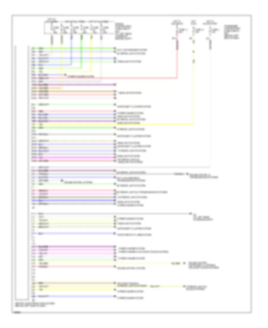
BODY CONTROL MODULES
Body Control Modules Wiring Diagram for Volvo V40 2004
List of elements for Body Control Modules Wiring Diagram for Volvo V40 2004:
- Air conditioning & interior lights systems
- Anti-lock brakes & transmissions systems
- Anti-lock brakes system
- Central electronic module (cem) (behind left side of dash)
- Computer data lines system
- Cruise control & transmissions systems
- Cruise control system
- Cruise control, instrument cluster & air conditioning systems
- E13
- Engine compartment fuse & relay box (at left rear corner of engine compt)
- Exterior lights & headlights systems
- Exterior lights & transmissions systems
- Exterior lights system
- F10
- F11
- F12
- F13
- F14
- F15
- F16
- Fuse 10a
- Fuse 12 15a
- Fuse 14 20a
- Fuse 15a
- Fuse 20a
- Fuse 4 10a
- G2 (at left rear of engine compt)
- Headlights system
- Hot at all times
- Hot in acc or on
- Hot in on
- Hot in on or start
- I22
- Instrument cluster system
- Interior lights & sound systems
- Interior lights system
- P10
- P11
- P12
- P13
- P14
- P15
- P16
- P17
- P18
- Passenger compartment fuse & relay box (behind left end of dash)
- Red
- Wiper/washer & air conditioning systems
- Wiper/washer system
 English