COMPUTER DATA LINES
Computer Data Lines Wiring Diagram for Volvo V40 2004
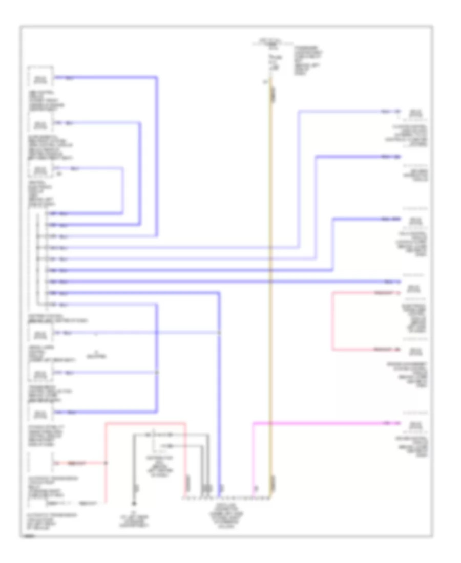
List of elements for Computer Data Lines Wiring Diagram for Volvo V40 2004:
- Abs control module (in right front corner of engine compartment)
- Automatic transmission vacuum pump (on left front of vehicle)
- Automatic transmission vacuum pump relay (in engine compt fuse & relay box)
- B19
- Central electronic module (cem) (behind left side of dash)
- Climate control module (ccm) (integral to a/c controls, in center of dash)
- Cruise control module (behind lower center of dash)
- Data link connector (under left side of dash, right of steering column)
- Distribution rail (behind left center of dash)
- Driver's information module
- Dynamic stability assistance (dsa) control module (behind right side of dash)
- E10
- Electronic immobilizer control module (behind left side of dash)
- Engine management system control module (behind lower center of dash)
- Fuse 15a
- G1 (at left rear of engine compartment)
- Hot at all times
- If equipped
- Nca
- Passenger compartment fuse & relay box (behind left side of dash)
- Solid state
- Transmission control module (tcm) (behind lower center of dash)
- Vgla control module (locks & alarm) (behind lower center of dash)
- Xenon lamps control module (under left rear seat)
 English