COMPUTER DATA LINES
Data Link Connector Wiring Diagram for Mercedes-Benz CLS550 2011

List of elements for Data Link Connector Wiring Diagram for Mercedes-Benz CLS550 2011:
- C30
- C41
- Can-b h
- Can-b l
- Can-c h
- Can-c l
- Can-d h
- Can-d l
- Central gateway control unit (under left side of dash)
- Data link connector (under left side of dash)
- Diag
- Emergency call system control unit (center front of trunk)
- Esp control unit (left rear of engine compt)
- Fuse 5a
- Fuse 7.5a
- High/low bus circuit
- Hot at all times
- Interior fuse box (left end of dash)
- Me-sfi (me) control module (right rear of engine compt)
- W15/2 (left front footwell)
- W15/3 (left rear of engine compt)
- X62-c3
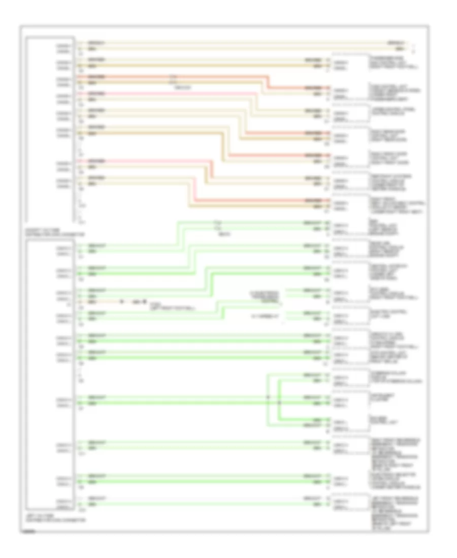
High/Low Bus Wiring Diagram (1 of 2) for Mercedes-Benz CLS550 2011
List of elements for High/Low Bus Wiring Diagram (1 of 2) for Mercedes-Benz CLS550 2011:
- Airmatic w/ ads control module (if equipped) (right front footwell)
- C10
- C11
- Can-b h
- Can-b l
- Can-c h
- Can-c l
- Central gateway control unit (under left side of dash)
- Cockpit voltage distributor (can) connector
- Dtr control unit (behind center of front grille)
- Eis (ezs) control unit
- Electric control unit (vgs)
- Electronic selector lever module control module (under center console)
- Esp control unit (left rear of engine compt)
- Etc (egs) control module (right front footwell)
- Instrument cluster
- Left front reversible emergency tensioning retractor (w/ reversible emergency tensioning retractor) (base of left front "b" pillar)
- Left voltage distributor (can) connector
- Me-sfi (me) control module (right rear of engine compt)
- Passenger side sam control unit (right front footwell)
- Restraint systems control module (under front of center console)
- Right front door control unit (right front door)
- Right front reversible emergency tensioning retractor (w/ reversible emergency tensioning retractor) (base of right front "b" pillar)
- Right front seat adjustment control module w/ memory (under right front seat)
- Right rear door control unit (right rear door)
- Steering column module (top of steering column)
- Upper control panel control module
- W/ 7-speed at
- W/ electronic transmission control
- W15/2 (left front footwell)
- Wss control unit (weight sensing system) (under front passenger's seat)
- X55/4-c21
- X62-c3
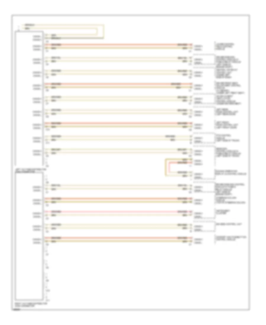
High/Low Bus Wiring Diagram (2 of 2) for Mercedes-Benz CLS550 2011
List of elements for High/Low Bus Wiring Diagram (2 of 2) for Mercedes-Benz CLS550 2011:
- C10
- C11
- Can-b h
- Can-b l
- Central gateway control unit (under left side of dash)
- Comand operating display & control module
- Comfort aac pushbutton control module
- Driver front seat adjustment control module (w/ memory) (under left front seat)
- Driver side sam control module w/ fuse & relay module (left side of engine compt)
- Eis (ezs) control unit
- Hs (sih) & seat ventilation control module (under driver's seat)
- I13
- Instrument cluster
- Left front door control unit (left front door)
- Left rear door control unit (left rear door)
- Left voltage distributor (can) connector
- Lower control field control module
- Pts control module (left side of trunk)
- Rear sam control module w/ fuse & relay module (left side of trunk)
- Right voltage distributor (can) connector
- Steering column module (top of steering column)