COMPUTER DATA LINES
Data Link Connector Wiring Diagram for Mercedes-Benz E320 1995

List of elements for Data Link Connector Wiring Diagram for Mercedes-Benz E320 1995:
- 15r
- A/c compressor control module (right rear side of engine compt)
- A/c pushbotton control module
- Anti- theft system
- Asd control module (e300 only)
- Cc/isa control module (in module box, on right rear of engine compt)
- Center console roll bar malfunction indicator lamp (e320 cabriolet)
- Cruise control system
- Data link connector (in module box, right rear of engine compt)
- Diagnostic circuit
- Diagnostic module test connection (e320 only) (california) (right rear corner of engine compt)
- E300
- E320
- E320 only
- Ea/cc/isa control module (in module box, on right rear of engine compt)
- Engine control module (hfm-sfi) (e320 only) (right rear of engine compt)
- Fuse & relay box (on left rear corner of engine compt)
- Fuse 16a
- Fuse 8a
- G202 (left side of i/p)
- Hot in acc run or start
- Hot in run or start
- Infrared control module
- Instrument cluster
- Isc control module (e300 only)
- Nca
- Nca led
- Nca switch
- Overvoltage protection relay module
- Pnk
- Roll bar control module (e320 cabriolet) (behind dash)
- Srs control module (under center console)
- Srs ind
- W/ ea
- W/o ea
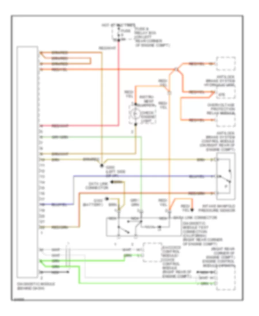
Diagnostic Socket Wiring Diagram for Mercedes-Benz E320 1995
List of elements for Diagnostic Socket Wiring Diagram for Mercedes-Benz E320 1995:
- (right rear corner of engine compt) engine control module (hfm-sfi)
- 87e
- Antilock brake system control module (on right rear of engine compt)
- Antilock brake system hydraulic unit
- Check engine light
- Data link connector
- Diagnostic module (behind dash)
- Diagnostic module test connection (california) (right rear corner of engine compt)
- Ea/cc/ics control module/ cc/ics control module (right rear of engine compt)
- Fuse & relay box (on left rear corner of engine compt)
- Fuse 8a
- G103 (battery)
- G202 (left side (of i/p)
- Hot at all times
- Instru- ment cluster
- Intake manifold pressure sensor
- Nca
- Overvoltage protection relay module