ENGINE PERFORMANCE
3.6L VIN 3
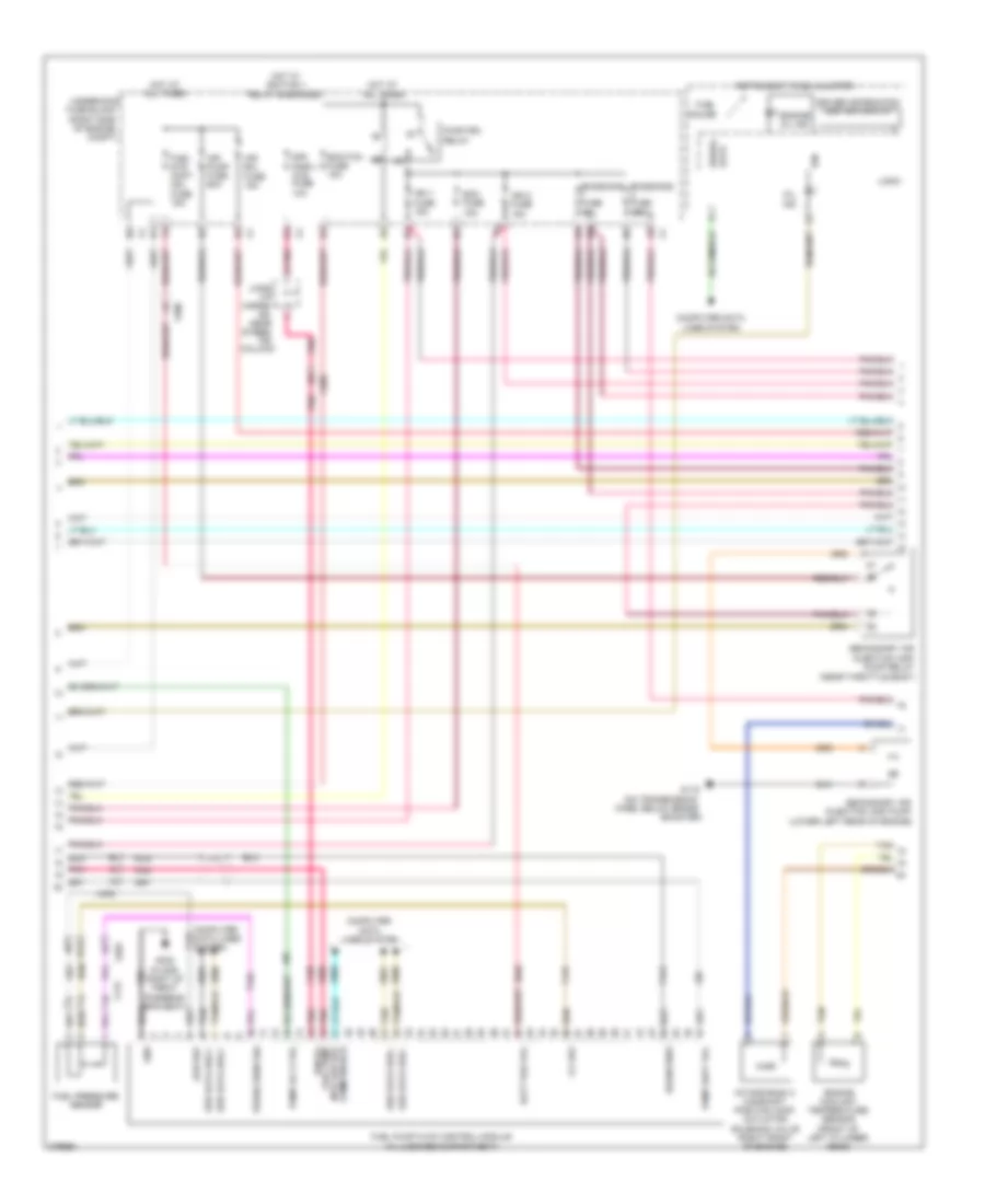
3.6L VIN 3, Engine Performance Wiring Diagram (1 of 5) for Chevrolet Impala LT 2012

List of elements for 3.6L VIN 3, Engine Performance Wiring Diagram (1 of 5) for Chevrolet Impala LT 2012:
- (2012)
- (left side of dash) accelerator pedal position sensor
- (under air cleaner) a/c refrigerant pressure sensor
- 5-v 1 ref
- 5-v 2
- 5-v 2 ref
- 5-v 3 ref
- 5-v vol 1 ref
- 5-v vol 4 ref
- A (2013)
- A/c compressor clutch rly ctrl
- A/c refrigerant press sens sig
- Air conditioning system
- Air sens sig
- App sens 1 sig
- App sens 2 sig
- Batt pos vol
- Block (right
- Bpp sig
- Brake pedal position (bpp) sensor (left side of dash)
- Brake pedal sw sig
- Canister vent solenoid valve (behind left rear wheelwell)
- Cnstr fuse 10a
- Computer data lines system
- Cooling fan rly ctrl
- Cooling fans system
- Ecm ign fuse 10a
- Engine control module (ecm) (inside air cleaner assembly)
- Evap conister vent sol ctrl
- Evaporative emission
- Exterior
- Exterior lights system
- Fuel composition sens sig
- Fuel level sens sig
- Fuel level sensor
- Fuel pump
- Fuel pump & sensor assembly (top of fuel tank)
- Fuel pump rly ctrl
- Fuel tank pressure sensor (fuel pump/ sender assembly)
- Fuel tank pressure sensor sig
- Fuse
- Gmlan serial data bus +
- Gmlan serial data bus -
- Hot at all times
- Hot w/ ignition main pcb relay energized
- I/p
- Ign vol
- Kick
- Lights system
- Low ref
- Low spd cooling fan rly ctrl
- Mil ctrl
- Nca
- Panel)
- Pnk
- Powertrain rly ctrl
- Sens low ref
- Starter rly ctrl
- Starting/charging system
- Tan
- Throttle pos sens sig
- Underhood fuse block (right side of engine compt)
- Wake-up sig
- X101
- X111
- X115
- X200
- X203
- X405
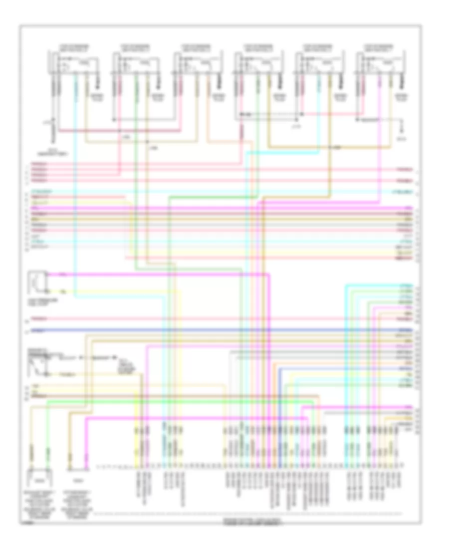
3.6L VIN 3, Engine Performance Wiring Diagram (2 of 5) for Chevrolet Impala LT 2012
List of elements for 3.6L VIN 3, Engine Performance Wiring Diagram (2 of 5) for Chevrolet Impala LT 2012:
- (i/p harne- ss, near steer- ing column)
- (lower left rear of engine)
- (on transmission
- 5-v ref
- Air pump fuse 60a
- Air sol fuse 15a
- B12
- Batt pos vol
- Booster)
- Case, below brake
- Comm enable
- Compt)
- Computer data lines system
- Drain wire
- Driver information center display
- Ecm fuse 15a
- Ecm/tcm fuse 15a
- Emissions fuse 15a
- Engine coolant temperature sensor (front of left cylinder head)
- Engine oil ind
- Fuel gauge
- Fuel pressure sensor
- Fuel pump
- Fuel pump flow control module (in luggage compartment)
- Fuel sys cont mdl fuse 15a
- G115
- G302 (floor, right of front passeng- er's seat)
- Gnd
- Hot at all times
- Hot w/ ignition 1 relay energized
- Ign
- Ign 1 fuse 15a
- Ign 2 fuse 15a
- Ignvol
- Instrument panel cluster
- Intake bank 2 camshaft position (cmp) actuator solenoid valve (right front of engine)
- J423
- Jx206
- Logic
- Low ref
- Mil ind
- Mtr low ref
- Nca
- Of engine
- Pnk
- Press sens sig
- Pump relay (near throttle body)
- Pump rly ctrl
- Pump supy vol
- Pwr/trn relay
- Secondary air injection (air)
- Secondary air injection (air) pump
- Ser data bus +
- Ser data bus -
- Serial data
- Sir/ displ- ays fuse 10a
- Tan
- Underhood fuse block (right side
- X115
- X200
- X203
- X405
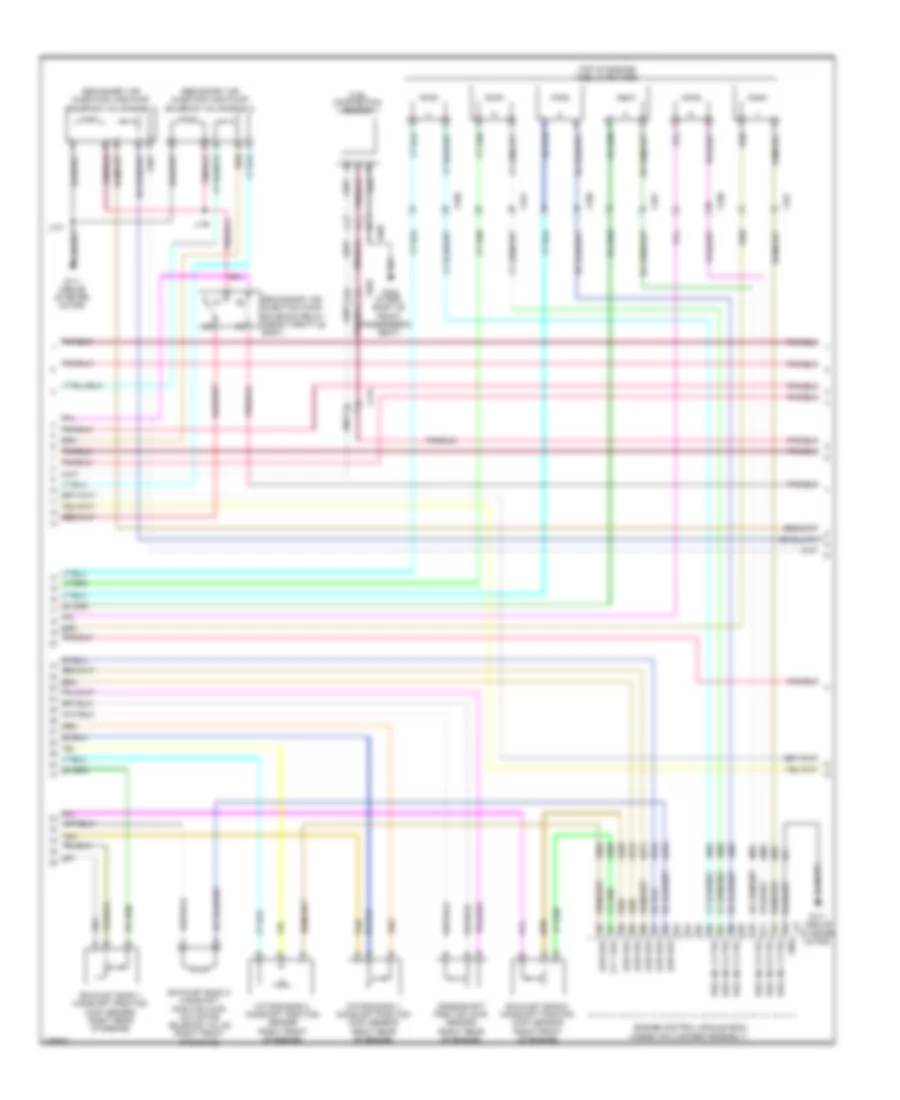
3.6L VIN 3, Engine Performance Wiring Diagram (3 of 5) for Chevrolet Impala LT 2012
List of elements for 3.6L VIN 3, Engine Performance Wiring Diagram (3 of 5) for Chevrolet Impala LT 2012:
- (above starter motor)
- (top of engine) ignition coil 1
- (top of engine) ignition coil 2
- (top of engine) ignition coil 3
- (top of engine) ignition coil 4
- (top of engine) ignition coil 5
- (top of engine) ignition coil 6
- 5-v 1 ref
- 5-volt 2 ref
- Actuator hi ctrl
- Actuator low ref
- Cam phaser ctrl
- Ect sens sig
- Engine control module (ecm) (inside air cleaner assembly)
- Engine oil pressure switch
- Exhaust bank 1 camshaft position (cmp) actuator solenoid valve (right rear of engine)
- Exhaust bank 1 sig
- Exhaust bank 2 sig
- Fuel inj 1 ctrl
- Fuel inj 2 ctrl
- Fuel inj 3 ctrl
- Fuel inj 4 ctrl
- Fuel inj 5 ctrl
- Fuel inj 6 ctrl
- G111
- G112
- G112 (near battery)
- High pressure fuel pump
- Ic 1 ctrl
- Ic 2 ctrl
- Ic 3 ctrl
- Ic 4 ctrl
- Ic 5 ctrl
- Ic 6 ctrl
- Intake bank 1 camshaft position (cmp) actuator solenoid valve (right rear of engine)
- Intake bank 1 sig
- Intake bank 2 sig
- J110
- J162
- J163
- J164
- J165
- Low ref
- Nca
- Oil press sw sig
- Pos sens sig
- Spark plug
- Tan
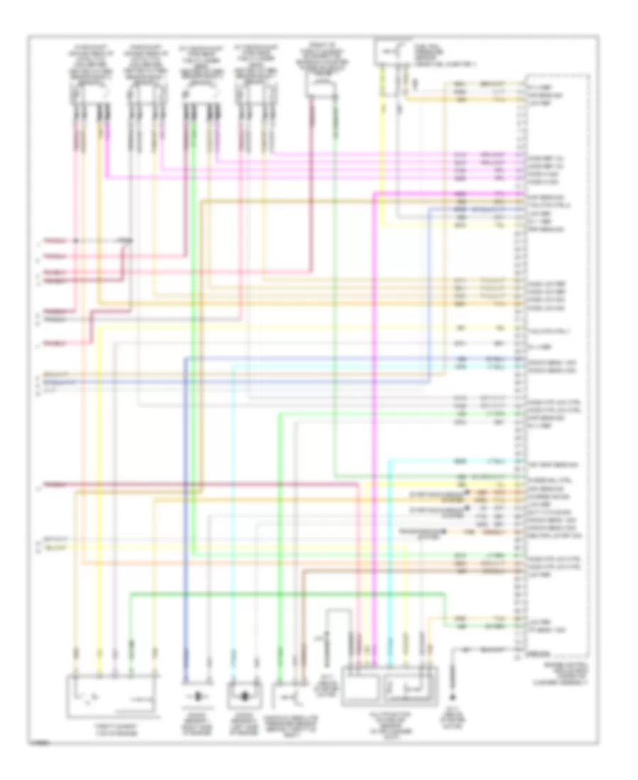
3.6L VIN 3, Engine Performance Wiring Diagram (4 of 5) for Chevrolet Impala LT 2012
List of elements for 3.6L VIN 3, Engine Performance Wiring Diagram (4 of 5) for Chevrolet Impala LT 2012:
- (inside air cleaner assembly)
- (top of engine) fuel injectors
- 5-v 1 ref
- Crankshaft position (ckp) sensor (right rear of engine)
- Engine control module (ecm)
- Exhaust bank 1 camshaft position (cmp) sensor (right rear of engine)
- Exhaust bank 2 camshaft position (cmp) actuator solenoid valve (right front of engine)
- Exhaust bank 2 camshaft position (cmp) sensor (right front of engine)
- Fuel composition sensor
- Fuel inj 1 ctrl
- Fuel inj 2 ctrl
- Fuel inj 3 ctrl
- Fuel inj 4 ctrl
- Fuel inj 5 ctrl
- Fuel inj 6 ctrl
- G111 (above starter motor)
- G302 (floor, right of front
- Gnd
- Intake bank 1 camshaft position (cmp) sensor (right rear of engine)
- Intake bank 2 camshaft position sensor (right front of engine)
- J101
- J175
- Low ref
- Passenger's
- Seat)
- Secondary air injection (air) pump solenoid valve bank 1
- Secondary air injection (air) pump solenoid valve bank 2
- Secondary air injection pump solenoid relay (near throttle body)
- Tan
- X115
- X160
- X161
- X203
- X405
3.6L VIN 3, Engine Performance Wiring Diagram (5 of 5) for Chevrolet Impala LT 2012
List of elements for 3.6L VIN 3, Engine Performance Wiring Diagram (5 of 5) for Chevrolet Impala LT 2012:
- (front of throttle body) evaporative emission canister purge solenoid valve
- (in exhaust, downstream of catalytic converter) heated oxygen sensor bank 1 sensor 2
- (in exhaust, downstream of catalytic converter) heated oxygen sensor bank 2 sensor 2
- (in the exhaust pipe near the cylinder head) heated oxygen sensor bank 1 sensor 1
- (in the exhaust pipe near the cylinder head) heated oxygen sensor bank 2 sensor 1
- (inside air
- (top of engine)
- 5-v 1 ref
- 5-v 2 ref
- 5-v 3 ref
- 5-v 4 ref
- A tan
- Air sens sig
- Air temp sens sig
- C tan
- Charge ind sig
- Cleaner assembly)
- Duty cycle sig
- Engine control module (ecm)
- Frp sens sig
- Fuel rail pressure sensor (near fuel injector 1)
- G111 (above starter motor)
- Ground
- Ho2s hi sig
- Ho2s htr low ctrl
- Ho2s low ref
- Ho2s low sig
- Ho2s ref vol
- J101
- J109
- Knock sens 1 sig
- Knock sens 2 sig
- Knock sensor 1 (right side of engine)
- Knock sensor 2 (left side of engine)
- Low ref
- Maf sens sig
- Manifold absolute pressure sensor (behind throttle body)
- Map sens sig
- Multifunction intake air sensor (in air cleaner duct)
- Nca
- Neutral start sig
- Purge sol ctrl
- Starting/charging system
- Tac mtr ctrl-1
- Tac mtr ctrl-2
- Tan
- Throttle body
- Tp sens 1 sig
- Transmissions system
- X160