ENGINE PERFORMANCE
2.4L VIN R
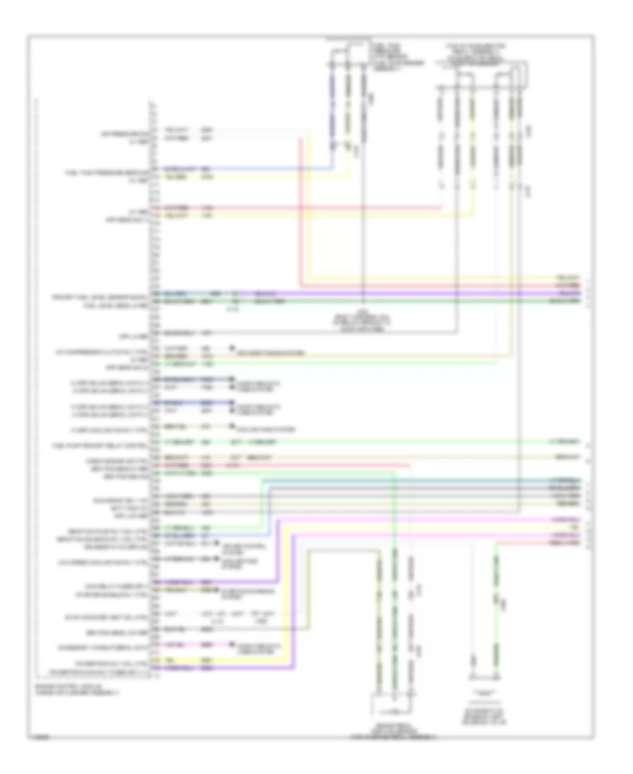
2.4L VIN R, Engine Controls Wiring Diagram (1 of 5) for Chevrolet Impala LT 2014

List of elements for 2.4L VIN R, Engine Controls Wiring Diagram (1 of 5) for Chevrolet Impala LT 2014:
- (body harness, 28.5 cm below branch to audio amplifier) j434
- (fuel pump/ sender assembly) fuel tank pressure sensor
- (on a/c line, under air cleaner) a/c refrigerant pressure sensor
- (right side of engine compt) underhood fuse block
- 5v ref
- 5v ref 1
- 5v ref 3
- 5v ref 4
- A/c sens sig
- Accelerator pedal position sensor (top of accelerator pedal assembly)
- Air conditioning system
- App sens sig 1
- App sig
- Check eng ind ctrl
- Cmpsr cltch
- Computer data lines system
- Cooling fans system
- Cruise control system
- Eng rly ctrl
- Engine control module (inside air cleaner assembly)
- Evaporative emission canister vent solenoid (right of fuel tank)
- Fan rly ctrl
- Fuel lvl sen sig
- Fuel lvl sens lo ref
- Fuel pres sens sig
- Fuel pump & level sensor assembly (top of fuel tank)
- Fuel pump rly ctrl
- Hi ser data bus (+)
- Hi ser data bus (-)
- Ign
- Ign 1 volt
- Low ref
- Pdl pos low ref
- Rly ctrl
- Sec air inj sol sig
- Solenoid ctrl
- Solenoid ctrl cruise/etc/tcc brake sig
- Starter rly ctrl
- Starting/charging system
- Wake-up ser data
- X115
- X117
- X210
- X350
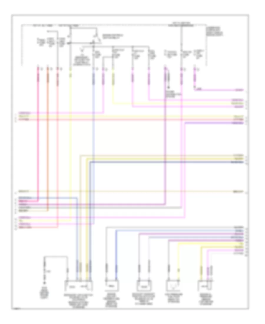
2.4L VIN R, Engine Controls Wiring Diagram (2 of 5) for Chevrolet Impala LT 2014
List of elements for 2.4L VIN R, Engine Controls Wiring Diagram (2 of 5) for Chevrolet Impala LT 2014:
- (body harness, 23.5 cm below branch to audio amplifier) j433
- (body harness, 44.3 cm from
- (left side of engine) (california) secondary air injection pump
- (rear center engine compt) g122
- (right side of engine compt) underhood fuse block
- A/c compressor clutch relay
- Active grille air shutter actuator (front center of of grille opening)
- Aero fuse 5a
- Cann vent fuse 5a
- Ccm fuse 20a
- Chassis control module (right rear luggage compt)
- Chassis control module)
- Communication enable
- Computer data lines system
- Cooling fan high speed relay
- Driver information center (dic) display
- Ecm batt fuse 5a
- Ecm ign fuse 5a
- Flp sens 5v ref
- Fpp rly ctrl
- From engine control ignition relay (diagram 4 of 5)
- Fuel pressure sensor (right side of fuel tank)
- G101 (center front engine compt)
- G405 (luggage compt right wheel well)
- Gmlan serial data
- Gnd
- Ground
- Hot at all times
- Hot w/ ignition main relay energized
- Ign
- Ign 1 volt run/crank
- Ind ctrl
- Instrument cluster
- J101
- J120
- J455
- Logic
- Low ref
- Low ref flp sens
- Mal- function lamp ind
- Oil level ind
- Power distribution system
- Press sens sig
- Red
- Sair pump fuse 50a
- Sair sol fuse 15a
- Secondary air injection pump relay (california)
- Secondary air injection solenoid valve relay (california)
- Serial data (+)
- Serial data (-)
- Shield extension
- Shutter valve sol ctrl
- Sply volt fuel pump
- Tcm/ ccm ign fuse 7.5a
- X105
- X114
- X115
- X150
- X350
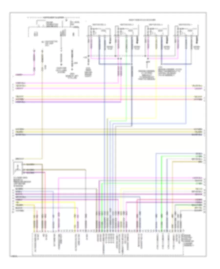
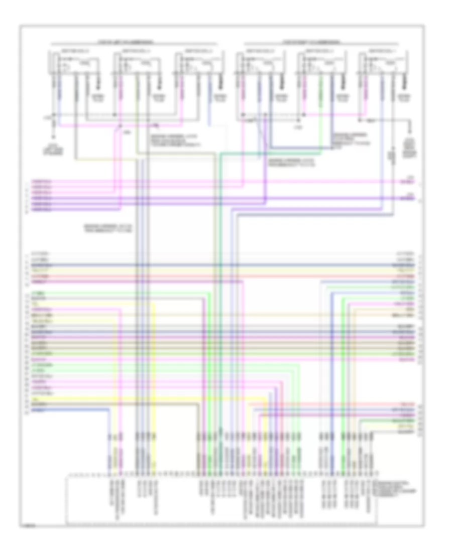
2.4L VIN R, Engine Controls Wiring Diagram (3 of 5) for Chevrolet Impala LT 2014
List of elements for 2.4L VIN R, Engine Controls Wiring Diagram (3 of 5) for Chevrolet Impala LT 2014:
- (engine harness, 5.2 cm from g122 toward evaporative emission purge solenoid valve)
- (left side of valve cover) ignition coil 1
- (left side of valve cover) ignition coil 2
- (left side of valve cover) ignition coil 3
- (left side of valve cover) ignition coil 4
- (right rear of engine) high pressure fuel pump
- 5v 1 ref
- 5v ref 2
- Cnrk pos sens sig
- Crankshaft position sensor (lower right side of engine block)
- Ect sens sig
- Engine control module (inside air cleaner assembly)
- Engine coolant temperature sensor (right rear side of engine)
- Engine oil pressure switch (rear top of engine)
- Exhaust bank 1 sig
- Exhaust camshaft position sensor (front of cylinder head)
- G122 (rear center engine compt)
- High ctrl
- Ic 1 ctrl
- Ic 2 ctrl
- Ic 3 ctrl
- Ic 4 ctrl
- Intake bank 1 sig
- Intake camshaft position sensor (front of cylinder head)
- J103
- J106 (engine harness, 16.9 cm from branch to rear of engine compt)
- J120
- J122
- Low ctrl
- Low ref
- Nca
- Oil pressure sw sig
- Secondary air injection solenoid valve cylinder 3/4
- Spark plug
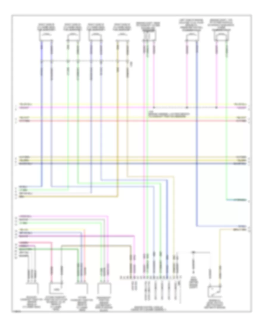
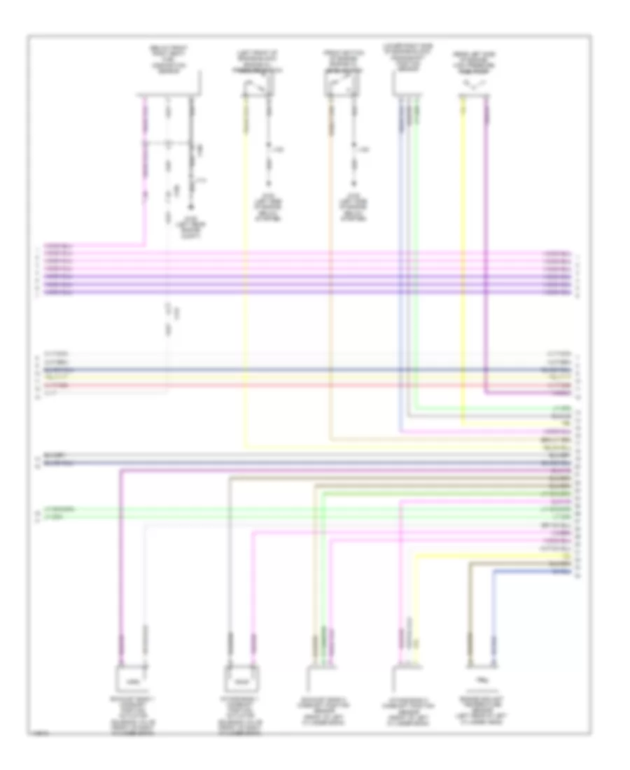
2.4L VIN R, Engine Controls Wiring Diagram (4 of 5) for Chevrolet Impala LT 2014
List of elements for 2.4L VIN R, Engine Controls Wiring Diagram (4 of 5) for Chevrolet Impala LT 2014:
- (left side of cylinder head)
- (right side of engine compt) underhood fuse block
- 5-volt ref 1
- Battery fuse block
- Coil odd fuse 15a
- Cooling fan low speed relay
- Ecm fuse 25a
- Engine control ignition relay
- Engine control module (inside air cleaner assembly)
- Exhaust camshaft position actuator solenoid valve (front of cylinder head)
- Exhaust solenoid (1)
- Fan rly a fuse 10a
- Fuel injector 1
- Fuel injector 1 ctrl
- Fuel injector 1 cynd
- Fuel injector 2
- Fuel injector 2 ctrl
- Fuel injector 2 cyl
- Fuel injector 3
- Fuel injector 3 ctrl
- Fuel injector 3 cyl
- Fuel injector 4
- Fuel injector 4 ctrl
- Fuel injector 4 cyl
- Fuse 250a
- G121 (front center engine compt)
- Hot at all times
- Intake camshaft position actuator solenoid valve (front of cylinder head)
- Intake solenoid (1)
- J108
- J121
- Low ref
- Non wlk pt fuse 10a
- Red
- Sig ground
- To a/c compressor clutch relay (diagram 2 of 5)
- X160
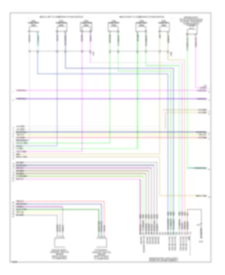
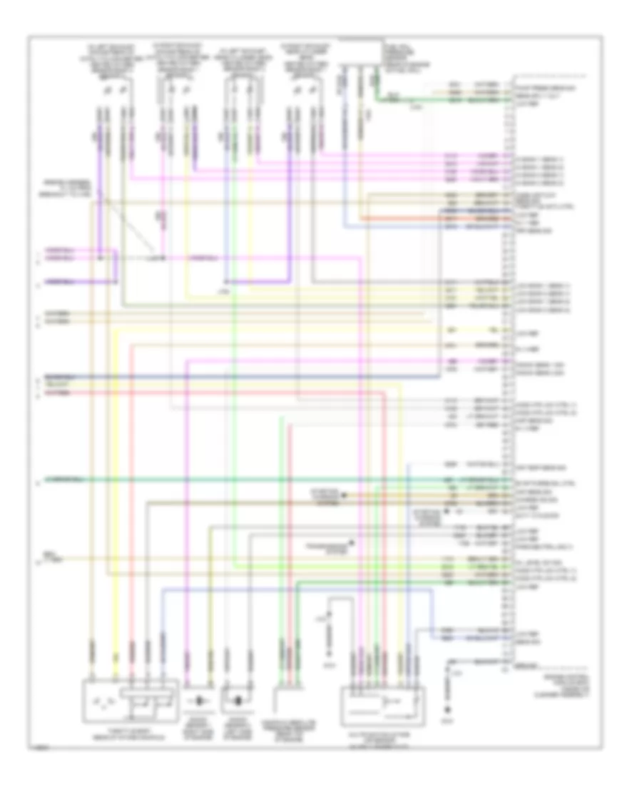
2.4L VIN R, Engine Controls Wiring Diagram (5 of 5) for Chevrolet Impala LT 2014
List of elements for 2.4L VIN R, Engine Controls Wiring Diagram (5 of 5) for Chevrolet Impala LT 2014:
- (california) secondary air injection solenoid valve cylinder 1/2
- (right side bottom of engine) heated oxygen sensor 2
- (right side of engine) heated oxygen sensor 1
- (top center of engine on fuel rail) fuel rail pressure sensor
- 5v ref 1
- 5v ref 3
- 5v ref 4
- Actuator ctrl close
- Actuator ctrl open
- Air press sens sig
- Air temp sens sig
- Charge ind ctrl
- Duty cycle sig
- Engine control module (inside air cleaner assembly)
- Evaporative emission purge solenoid valve (engine compt, mounted to left side of cylinder head)
- Frp sens sig
- G121 (front center engine compt)
- G122 (rear center engine compt)
- Ground
- Ho2s b1 s1
- Ho2s b1 s2
- J117 (engine harness, 11.9 cm from branch to rear of engine components)
- J120
- J121
- Knock sens low ref
- Knock sens sig
- Knock sensor
- Logic
- Low ref
- Low sig bank 1 sens (1)
- Low sig bank 2 sens (2)
- Maf low ref
- Maf sens sig
- Manifold absolute pressure sensor (left side of engine)
- Map low ref
- Map sens sig
- Mass air flow/intake air temperature sensor (mounted to upper air cleaner assembly)
- Nca
- Park/neutral sig
- Sens low ref
- Solenoid ctrl
- Sply volt
- Starting/charging system
- Throttle body (top of intake manifold)
- Tp sens sig
- Transmissions system
- X114
- X160
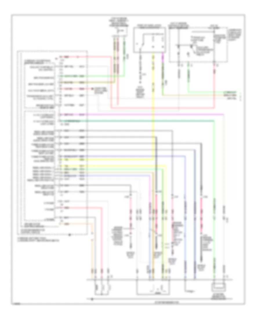
2.4L VIN R, Hybrid System Wiring Diagram (1 of 4) for Chevrolet Impala LT 2014
List of elements for 2.4L VIN R, Hybrid System Wiring Diagram (1 of 4) for Chevrolet Impala LT 2014:
- (engine harness, 4 cm from branch to engine control module to g122)
- (engine harness, 4 cm pnk from ignition coil 3 to ignition coil 2) j122
- (part of hood latch) hood ajar switch
- (top of brake pedal assembly) brake pedal position sensor
- Aux wkup serial data
- Auxiliary transmission fluid pump relay
- Bas pwr inverter fuse 175a
- Brake position snsr 5v ref
- Brk pos snsr low ref
- Brk pos snsr sig
- Computer data lines system
- Coolant pump relay coil control
- Driver motor control module 1
- G101 (engine compt center front)
- Hi volt interlock loop lo ref
- Hi volt interlock loop signal
- Hot at all times
- Hot w/ engine controls ignition relay energized
- Hybrid/ev battery pack (luggage compt, behind rear seats)
- Hybrid/ev powertrain control module
- J101
- J121 (engine harness, 11.2 cm from main bundle)
- J123
- J124
- J126
- J127
- J128
- J129
- Nca
- Pnk
- Red
- Resolver cosine signal drain wire
- Resolver motor drain wire
- Resolver mtr positive
- Resolver signal 1
- Resolver signal 2
- Resolver signal 3
- Resolver signal 4
- Resolver sine signal drain wire
- Starter/ generator cable cover
- Starter/generator
- Starter/generator control module
- Three phase motor temp drain wire
- Three phase motor temp low ref
- Three phase motor temp sig hood open sw sig
- Trans aux pmp fuse 30a
- Transmission auxiliary oil pump rly ctrl
- U phase
- Underhood fuse block (right side of engine compt)
- V phase
- W phase
- X10
- X115
- X150
- X210
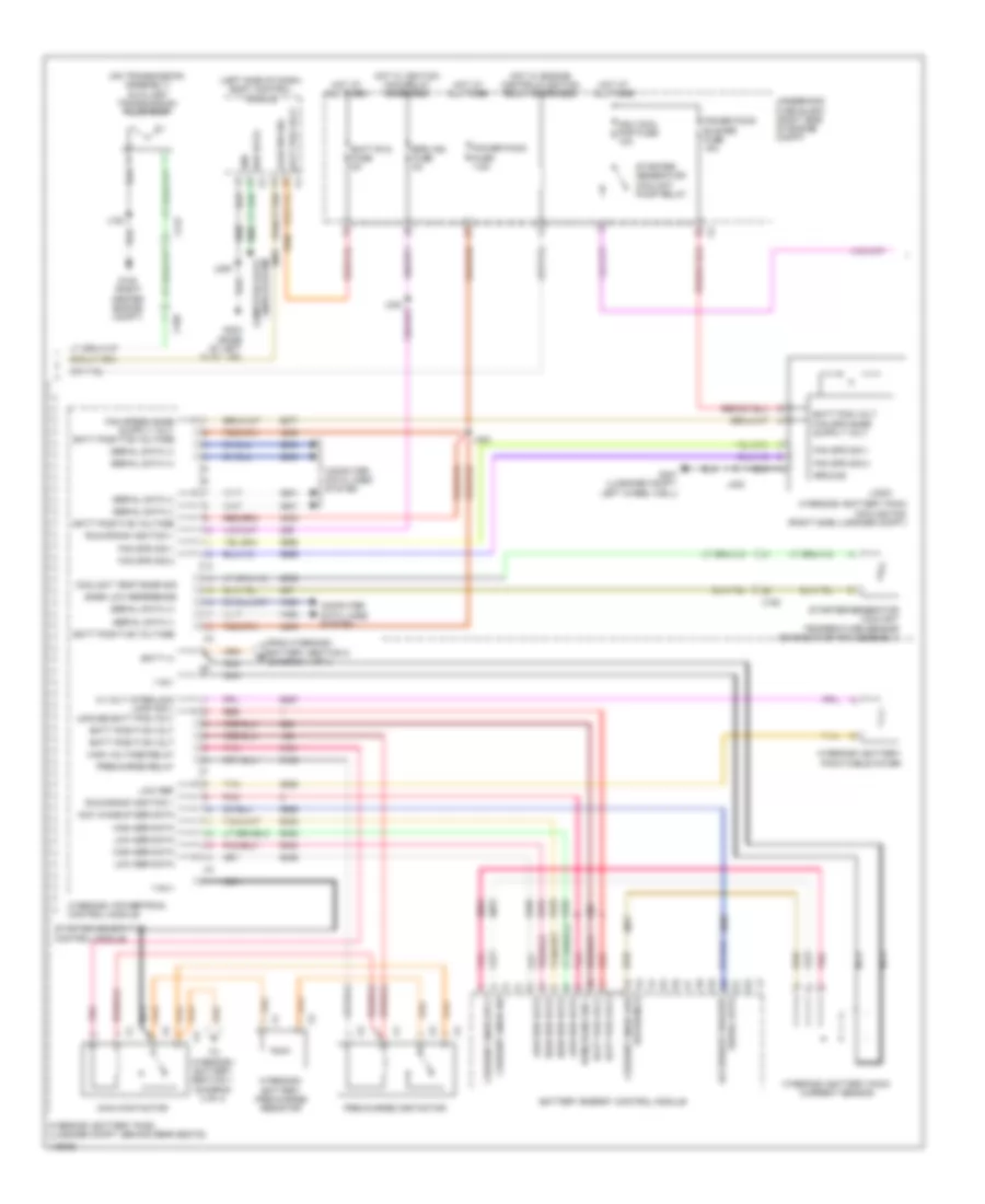
2.4L VIN R, Hybrid System Wiring Diagram (2 of 4) for Chevrolet Impala LT 2014
List of elements for 2.4L VIN R, Hybrid System Wiring Diagram (2 of 4) for Chevrolet Impala LT 2014:
- (left side of dash) body control module
- (on transmission assembly) auxiliary transmission fluid pump
- 115v+
- 115v-
- Acc wakeup ser data
- Ajar sw sig
- Batt (+)
- Batt pos volt
- Batt positive volt
- Batt positive voltage
- Batt rvc fuse 5a
- Battery energy control module
- Bpim ign fuse 5a
- Computer data lines system
- Coolant temp snsr sig
- Current snsr low
- Current snsr sig
- Current snsr sply
- Fan spd sig 1
- Fan spd sig 2
- From hybrid/ev battery section 2 (diagram 4 of 4)
- G122 (right center engine compt)
- G203 (base of left "a" pillar)
- G401 (luggage compt, left wheel well)
- Gnd
- Ground
- Hi volt interlock loop sig 1
- High ser data
- High voltage relay
- Hot at all times
- Hot w/ engine controls ignition relay energized
- Hot w/ ignition main relay energized
- Hybrid/ev battery pack (luggage compt, behind rear seats)
- Hybrid/ev battery pack cable cover
- Hybrid/ev battery pack cooling fan (right side luggage compt)
- Hybrid/ev battery pack current sensor
- Hybrid/ev battery pre-charge resistor
- Hybrid/ev powertrain control module
- J120
- J209
- J400
- J402
- Logic
- Low ref
- Low ser data
- Main contactor
- Mgu cool pmp fuse 10a
- Nca
- Pnk
- Power pack blower fuse 15a
- Power pack fuse 7.5a
- Pre-charge contactor
- Precharge relay
- Red
- Reference
- Run/crank ign 1
- Run/crank ignition 1
- Ser data
- Serial data (+)
- Serial data (-)
- Serial data accessory wakeup
- Snsr low reference
- Starter/ generator coolant pump relay
- Starter/generator control module
- Starter/generator coolant temperature sensor (on radiator fan assembly)
- Tan
- To hybrid/ev battery section 1 (diagram 3 of 4)
- Underhood fuse block (right side of engine compt)
- Unfuse batt pos volt
- X115
- X150
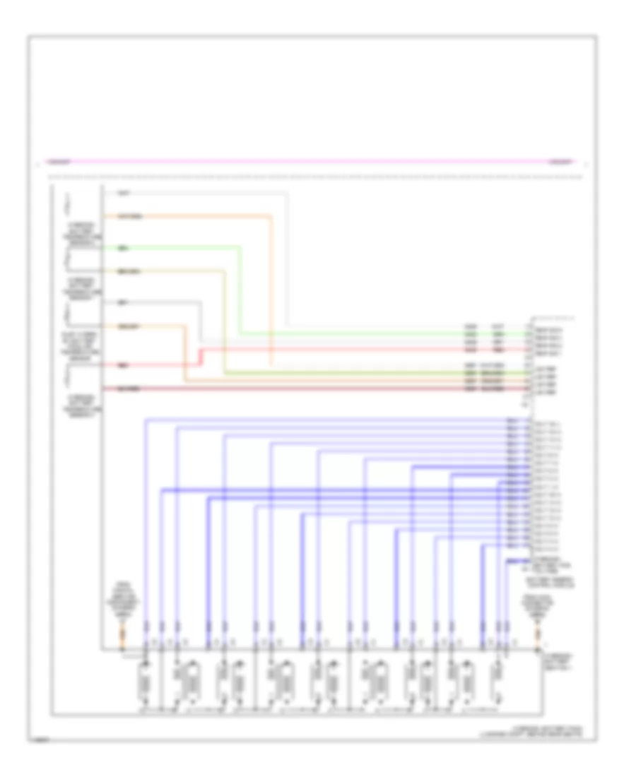
2.4L VIN R, Hybrid System Wiring Diagram (3 of 4) for Chevrolet Impala LT 2014
List of elements for 2.4L VIN R, Hybrid System Wiring Diagram (3 of 4) for Chevrolet Impala LT 2014:
- Battery energy control module
- From main connector (diagram 2 of 4)
- From manual service disconnect (diagram 4 of 4)
- Hybrid/ev battery pack (luggage compt, behind rear seats)
- Hybrid/ev battery pos voltage
- Hybrid/ev battery section 1
- Hybrid/ev battery temperature sensor 1
- Hybrid/ev battery temperature sensor 2
- Hybrid/ev battery temperature sensor 3
- Inlet hybrid/ ev battery pack air temperature sensor
- Low ref
- Red
- Temp sig 1
- Temp sig 2
- Temp sig 4
- Temp sig 5
- Volt 1 (+)
- Volt 10 (+)
- Volt 11 (+)
- Volt 12 (+)
- Volt 13 (+)
- Volt 14 (+)
- Volt 15 (+)
- Volt 16 (+)
- Volt 16 (-)
- Volt 2 (+)
- Volt 3 (+)
- Volt 4 (+)
- Volt 5 (+)
- Volt 6 (+)
- Volt 7 (+)
- Volt 8 (+)
- Volt 9 (+)
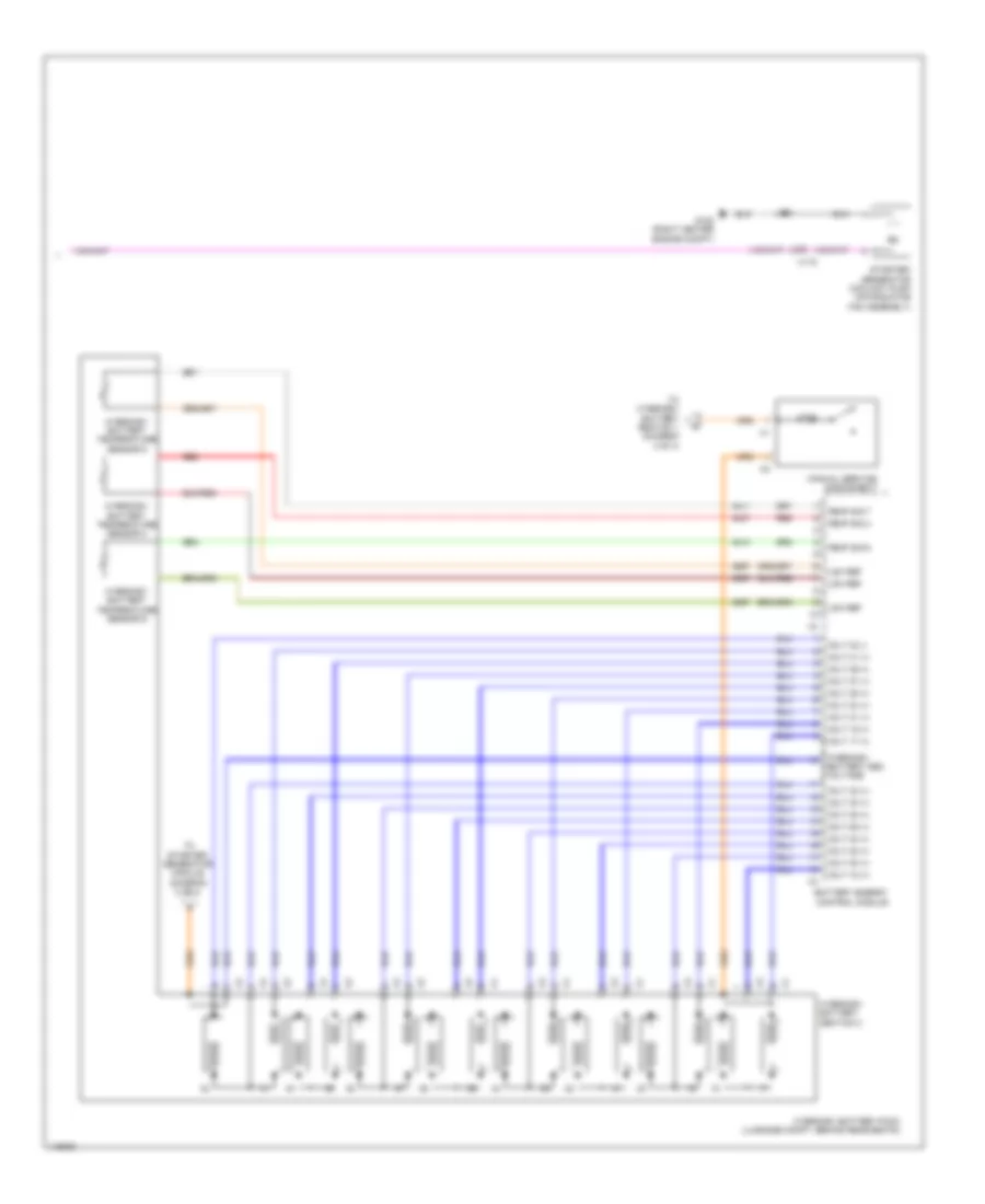
2.4L VIN R, Hybrid System Wiring Diagram (4 of 4) for Chevrolet Impala LT 2014
List of elements for 2.4L VIN R, Hybrid System Wiring Diagram (4 of 4) for Chevrolet Impala LT 2014:
- 125a
- Battery energy control module
- G122 (right center engine compt)
- Hybrid/ev battery pack (luggage compt, behind rear seats)
- Hybrid/ev battery section 2
- Hybrid/ev battery temperature sensor 4
- Hybrid/ev battery temperature sensor 5
- Hybrid/ev battery temperature sensor 6
- J120
- Low ref
- Manual service disconnect
- Red
- Starter/ generator coolant pump (on radiator fan assembly)
- T0 starter/ generator module (diagram 2 of 4)
- Temp sig 3
- Temp sig 6
- Temp sig 7
- To hybrid/ev battery section 1 (diagram 3 of 4)
- Volt 17 (+)
- Volt 18 (+)
- Volt 19 (+)
- Volt 20 (+)
- Volt 21 (+)
- Volt 22 (+)
- Volt 23 (+)
- Volt 24 (+)
- Volt 25 (+)
- Volt 26 (+)
- Volt 27 (+)
- Volt 28 (+)
- Volt 29 (+)
- Volt 30 (+)
- Volt 31 (+)
- Volt 32 (+)
- Volt 32 (-)
- X115
2.5L VIN L
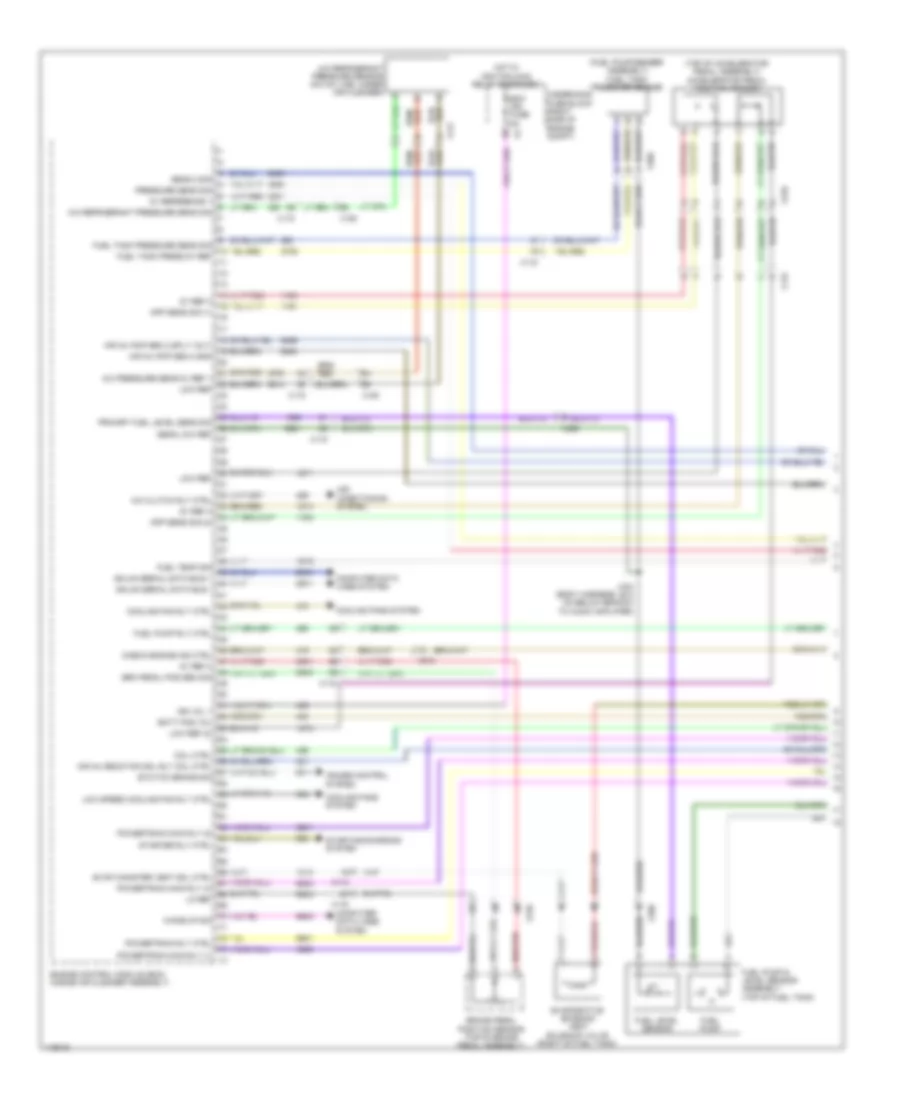
2.5L VIN L, Engine Performance Wiring Diagram (1 of 6) for Chevrolet Impala LT 2014
List of elements for 2.5L VIN L, Engine Performance Wiring Diagram (1 of 6) for Chevrolet Impala LT 2014:
- (top of accelerator pedal assembly) accelerator pedal position sensor
- 5-v ref
- 5v ref
- A/c compressor clutch rly ctrl
- Accessory wakeup serial data
- Air conditioning system
- Air pressure sig
- App lo ref
- App low ref
- App sens sig (1)
- App sens sig (2)
- Batt pos vol
- Brake pedal position sensor (top of brake pedal assembly)
- Brk pos sen sig
- Brk pos sens 5v ref
- Brk pos sens low ref
- Check engine ind ctrl
- Computer data lines system
- Cooling fans system
- Cruise control system
- Cruise\etc\tcc brk sig
- Engine control module (inside air cleaner assembly)
- Evap conister vent sol ctrl
- Evaporative emission vent solenoid valve
- Fuel level sens lo ref
- Fuel pump primary relay control
- Fuel tank pressure (ftp) sensor (fuel pump/sender assembly)
- Fuel tank pressure sens sig
- Hi spd cooling fan rly ctrl
- Hi spd gmlan serial data (+)
- Hi spd gmlan serial data (-)
- J434 (body harness, 28.5 cm below branch to audio amplifier)
- Low speed cooling fan rly ctrl
- Main relay fused sply
- Powertrain main rly fused sply (1)
- Powertrain rly coil ctrl
- Primary fuel level sensor signal
- Reaction pump rly coil ctrl
- Reaction solenoid rly coil ctrl
- Run/crank ign 1 vol
- Starter enable rly ctrl
- Starting/charging system
- X115
- X210
- X350
2.5L VIN L, Engine Performance Wiring Diagram (2 of 6) for Chevrolet Impala LT 2014
List of elements for 2.5L VIN L, Engine Performance Wiring Diagram (2 of 6) for Chevrolet Impala LT 2014:
- (right side of engine) secondary air injection pump
- 5 volt ref
- Batt pos volt
- Chassis control module (right rear luggage compt)
- Computer data lines system
- From engine controls ignition relay (diagram 3 of 6)
- Fuel level sensor
- Fuel pressure sensor (right side of fuel tank)
- Fuel pump
- Fuel pump & level sensor assembly (top of fuel tank)
- G122 (rear center engine compt)
- G405 (luggage compt, right wheel well)
- Ground
- Hot at all times
- Ign 1 volt
- J120
- J455 (body harness, 44.3 cm from chassis control module)
- Low ref
- Nca
- Red
- Rly ctrl
- Sair pump fuse 50a
- Sair sol fuse 15a
- Secondary air injection pump relay (california emission system)
- Secondary air injection solenoid valve relay (california emission system)
- Sensor signal
- Serial data (+)
- Serial data (-)
- Serial data enable
- Shield exten
- Underhood fuse block (right side of engine compt)
- X114
- X115
- X350
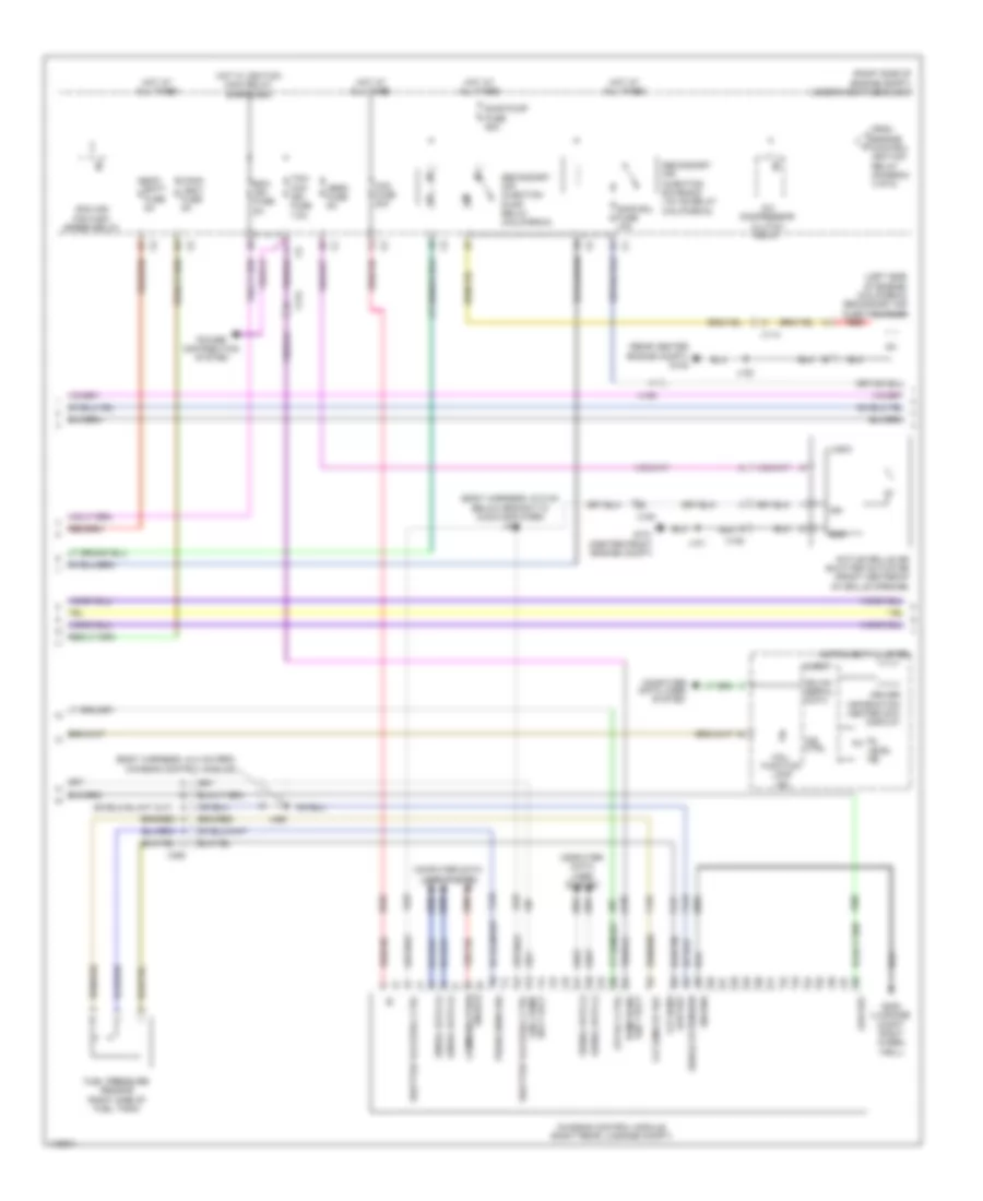
2.5L VIN L, Engine Performance Wiring Diagram (3 of 6) for Chevrolet Impala LT 2014
List of elements for 2.5L VIN L, Engine Performance Wiring Diagram (3 of 6) for Chevrolet Impala LT 2014:
- Cann vent fuse 10a
- Coil odd fuse 15a
- Disply ign fuse 5a
- Ecm batt fuse 5a
- Ecm fuse 20a
- Ecm ign fuse 5a
- Engine controls ignition relay
- Engine coolant temperature sensor (rear top of engine)
- Engine oil pressure sensor (top center of engine)
- Exhaust camshaft position actuator solenoid valve (rear of cylinder head)
- Fscm fuse 20a
- G122 (rear center engine compt)
- High pressure fuel pump (rear top of engine)
- Hot at all times
- Hot w/ ignition main relay energized
- J120
- J339
- Non wlk ft fuse 10a
- Non wlk pt fuse 10a
- Power distribution system
- Secondary air injection solenoid valve (california emission system) (rear left side of engine)
- Tcm/ccm ign fuse 7.5a
- To secondary air injection pump relay (diagram 2 of 6)
- Underhood fuse block (right side of engine compt)
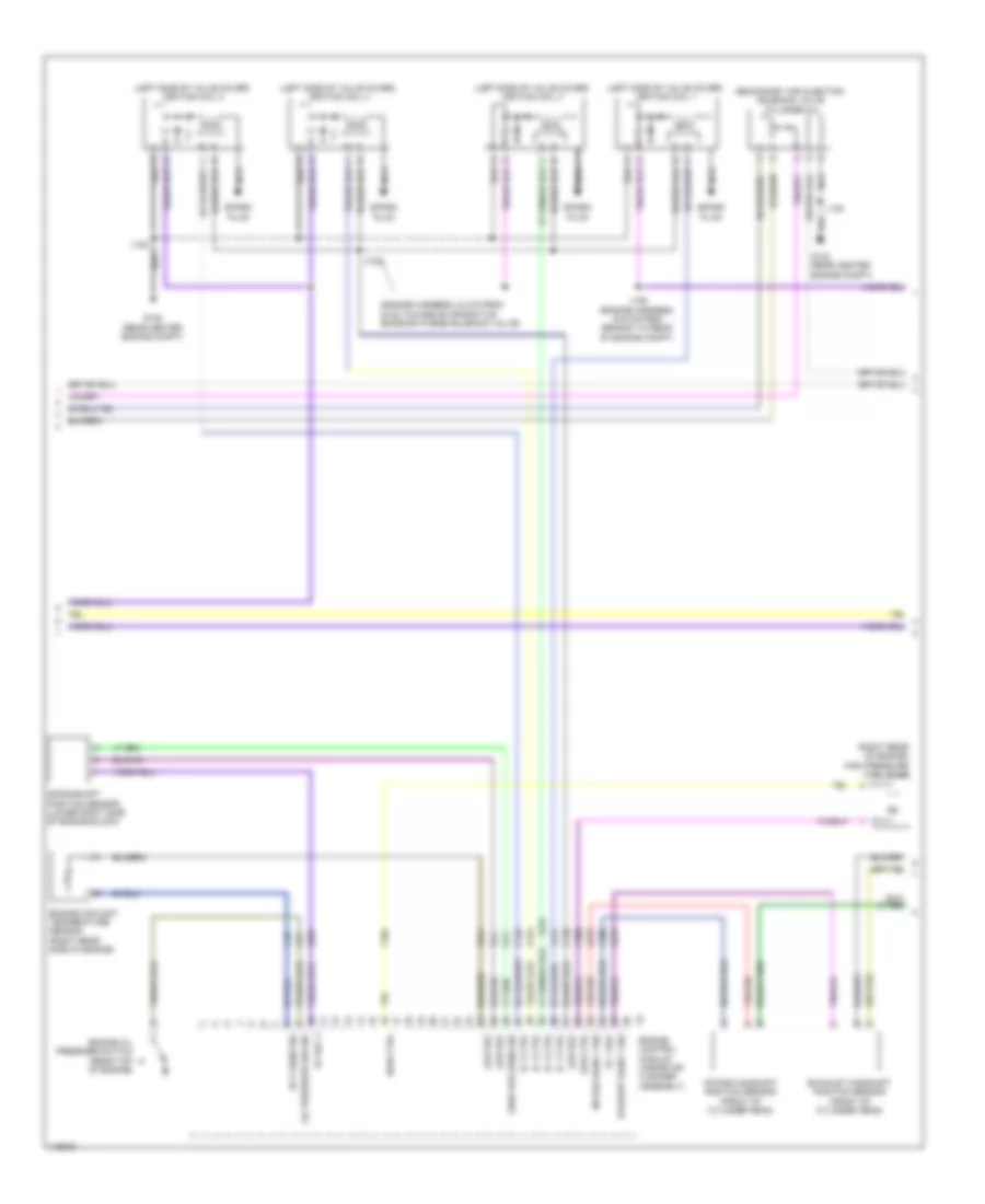
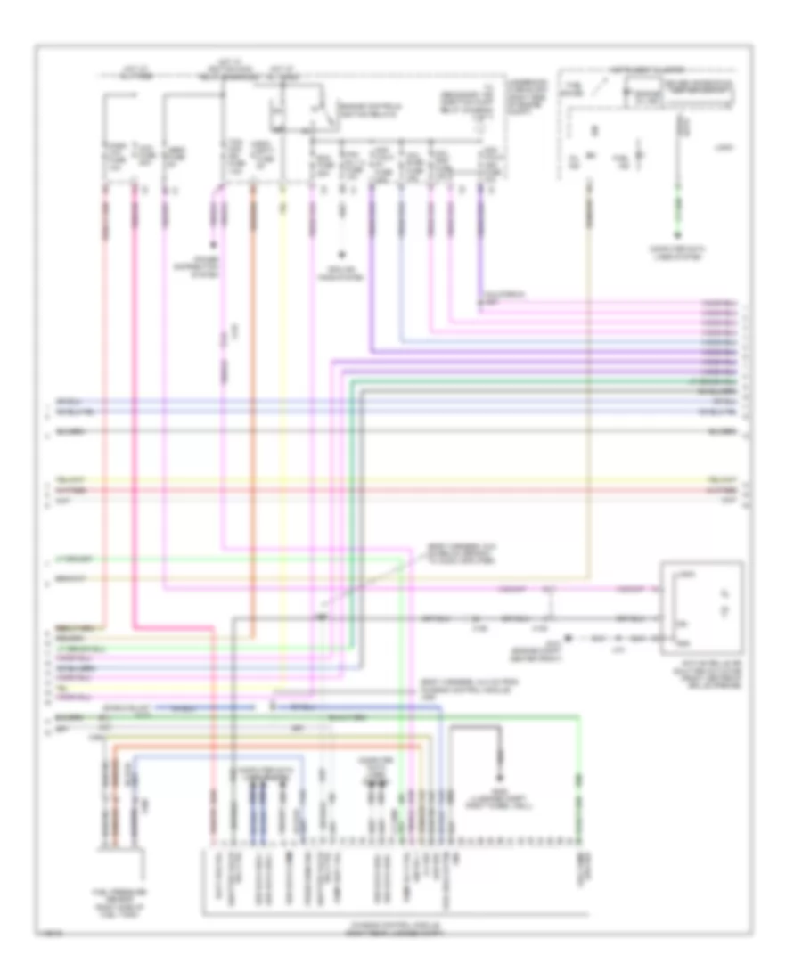
2.5L VIN L, Engine Performance Wiring Diagram (4 of 6) for Chevrolet Impala LT 2014
List of elements for 2.5L VIN L, Engine Performance Wiring Diagram (4 of 6) for Chevrolet Impala LT 2014:
- (engine harness, 6.1 cm from breakout to crankshaft position sensor)
- (right side of valve cover)
- 5v ref
- Actuator hi ctrl
- Actuator low ctrl
- Camshaft pos intake
- Computer data lines system
- Crankshaft 60x sens volt
- Crankshaft sens sig
- Ctrl cylinder 1
- Ctrl cylinder 2
- Ctrl cylinder 3
- Ctrl cylinder 4
- Cylinder head engine oil pressure sensor (top center of engine)
- Data (-)
- Driver information center (dic)
- Ect sens sig
- Engine control module (inside air cleaner assembly)
- Exhaust sens (1)
- Exhaust sol (1)
- G122 (rear center engine compt)
- G203 (base of left "a" pillar)
- Gnd
- Ic ctrl (1)
- Ic ctrl (2)
- Ic ctrl (3)
- Ic ctrl (4)
- Ign 1 volt
- Ignition coil 1
- Ignition coil 2
- Ignition coil 3
- Ignition coil 4
- Instrument cluster
- Intake sol (1)
- J103 (engine harness, 10.5 cm from the breakout to control solenoid valve assembly)
- J106
- J122
- J209
- Lo ref
- Logic
- Low ref
- Low ref bank 1
- Malfunction ind lamp (mil)
- Nca
- Oil level ind
- Oil press sens sig
- Sens lo ref
- Serial most
- Sig
- Spark plug
- Sply volt
- X210
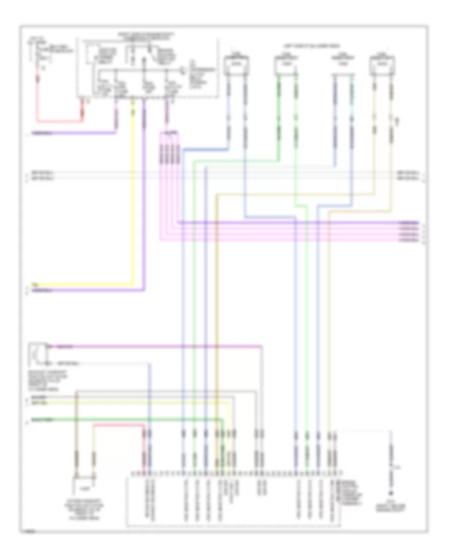
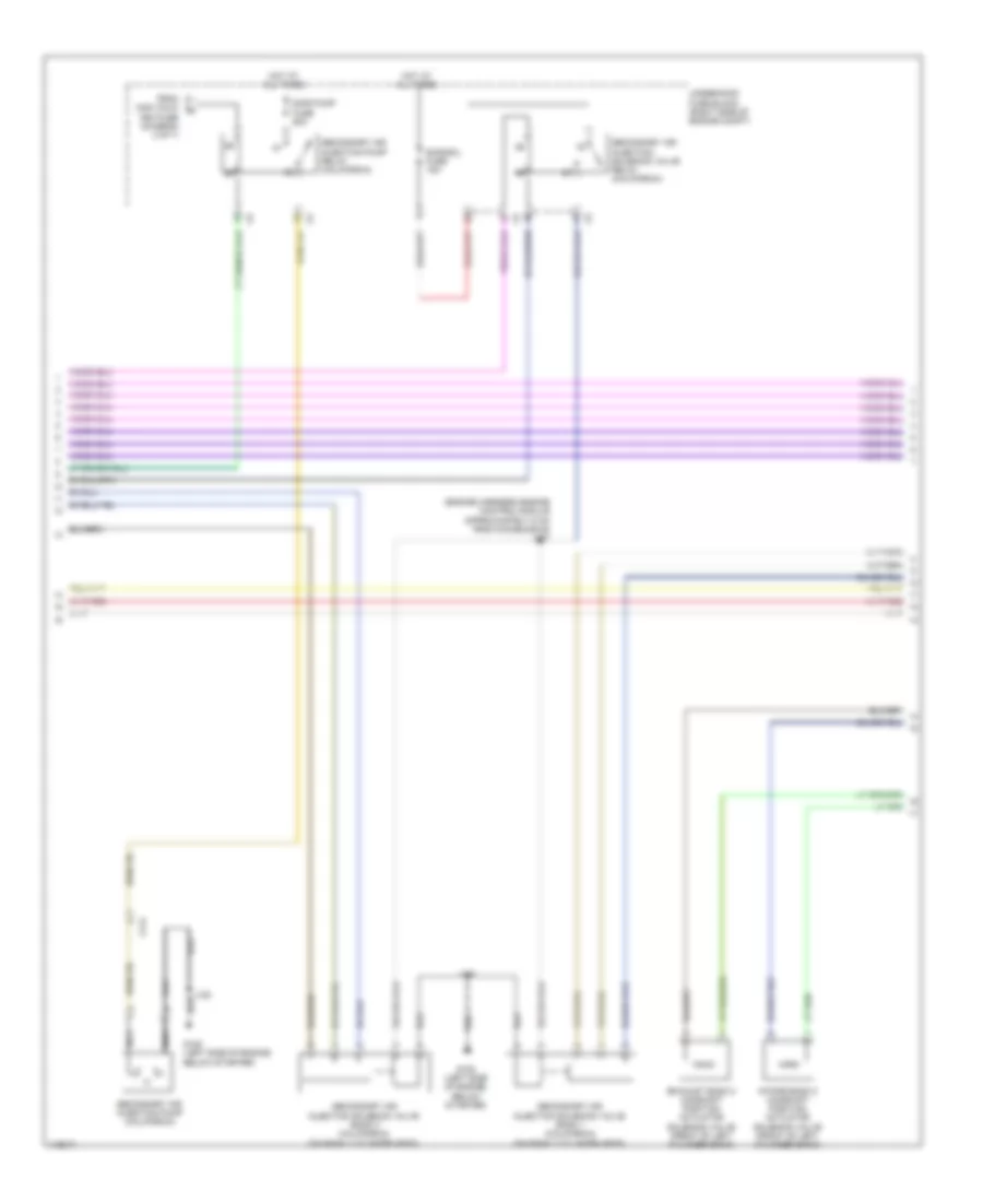
2.5L VIN L, Engine Performance Wiring Diagram (5 of 6) for Chevrolet Impala LT 2014
List of elements for 2.5L VIN L, Engine Performance Wiring Diagram (5 of 6) for Chevrolet Impala LT 2014:
- (engine compt, rear of camshaft cover) rocker arm actuator
- (engine compt, top of intake manifold) evaporative emission purge solenoid valve
- (left side of engine, mounted to oil pump) engine oil pressure control solenoid valve
- (right side of cylinder head) fuel injector 1
- (right side of cylinder head) fuel injector 2
- (right side of cylinder head) fuel injector 3
- (right side of cylinder head) fuel injector 4
- Crankshaft position sensor (lower right side of engine block)
- Engine control module (inside air cleaner assembly)
- Engine oil level switch (bottom right center of engine)
- Exhaust camshaft position sensor (rear of cylinder head)
- G121 (rear center engine compt)
- Gnd
- Intake camshaft position actuator solenoid valve (rear of cylinder head)
- Intake camshaft position sensor (rear of cylinder head)
- J108 (engine harness, 4 cm from branch to camshaft position sensors)
- J121
- Low ref
- Sply cylinder 1
- Sply cylinder 2
- Sply cylinder 3
- Sply cylinder 4
- Step cam a ctrl
- Step cam b ctrl
- X160
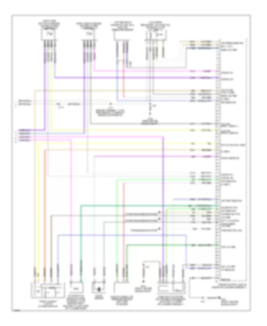
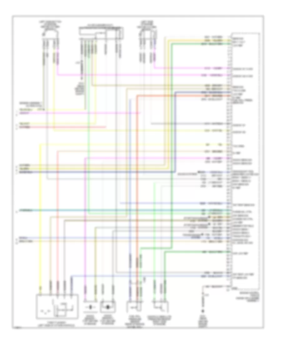
2.5L VIN L, Engine Performance Wiring Diagram (6 of 6) for Chevrolet Impala LT 2014
List of elements for 2.5L VIN L, Engine Performance Wiring Diagram (6 of 6) for Chevrolet Impala LT 2014:
- (engine harness, 7 cm from g122)
- (in air cleaner duct) multifunction intake air sensor
- (left side bottom of engine) heated oxygen sensor 2
- (left side of engine) heated oxygen sensor 1
- 5v ref
- 5v ref fuel rail press sens sig
- Air temp low ref
- Air temp sens sig
- Bank 1 sens (1)
- Bank 1 sens (2)
- Charge ind ctrl
- Command sig
- Crankshaft pos sens replicated sig
- Engine control module (inside air cleaner assembly)
- Fuel rail pressure sensor (rear of engine on fuel rail)
- G121 (rear center engine compt)
- Generator field
- Gnd
- Ho2s b1 s1
- Ho2s b1 s1 hi sig
- Ho2s b1 s2
- Ho2s b1 s2 hi sig
- J107
- J121
- Knock sens 1
- Knock sens 2
- Knock sens sig
- Knock sensor 1 (top center of engine)
- Knock sensor 2 (top center of engine)
- Logic
- Low ref
- Maf sens sig
- Manifold absolute pressure sensor (right side of engine)
- Map low ref
- Map sens sig
- Oil level sw sig
- Purge sol ctrl
- Sens sig
- Sound systems
- Sply volt
- Starting/charging system
- Tac close
- Tac open
- Throttle body (left side of intake manifold)
- Tp sens sig
- Trans p/n sig 1
- Transmissions system
- X160
3.6L VIN 3
3.6L VIN 3, Engine Performance Wiring Diagram (1 of 7) for Chevrolet Impala LT 2014
List of elements for 3.6L VIN 3, Engine Performance Wiring Diagram (1 of 7) for Chevrolet Impala LT 2014:
- (fuel pump/sender assembly) fuel tank pressure sensor
- (top of accelerator pedal assembly) accelerator pedal position sensor
- 5v ref 2
- 5v ref 3
- 5v ref 4
- 5v reference 1
- A/c clutch rly ctrl
- A/c pressure sens 5v ref 1
- A/c refrigerant pressure sens sig
- A/c refrigerant pressure sensor (on a/c line, under air cleaner)
- Air conditioning system
- Air inj pmp sen 2 gnd
- Air inj pmp sen 2 sply volt
- Air inj reaction sol rly c0il ctrl
- App sens sig (1)
- App sens sig (2)
- Batt pos vol
- Brake pedal position sensor (top of brake pedal assembly)
- Brk pedal pos sen sig
- Check engine ind ctrl
- Coil ctrl
- Computer data lines system
- Cooling fan rly ctrl
- Cooling fans system
- Cruise control system
- Ecm ign fuse 5a
- Engine control module (ecm) (inside air cleaner assembly)
- Etc/tcc brake sig
- Evap canister vent sol ctrl
- Evaporative emission vent solenoid valve (right of fuel tank)
- Fuel level sensor
- Fuel pump
- Fuel pump & level sensor assembly (top of fuel tank)
- Fuel pump rly ctrl
- Fuel tank press 5v ref
- Fuel tank pressure sens sig
- Fuel temp sig
- Gmlan serial data bus +
- Gmlan serial data bus -
- Hot w/ ignition main relay energized
- Ign vol 1
- J434 (body harness, 28.5 cm below branch to audio amplifier)
- Lo ref
- Low ref
- Low ref (2)
- Low speed cooling fan rly ctrl
- Powertrain main rly (1)
- Powertrain main rly (2)
- Powertrain main rly (3)
- Powertrain rly ctrl
- Pressure sens sig
- Primary fuel level sens sig
- Sens 2 sig
- Sens low ref
- Starter rly ctrl
- Starting/charging system
- Underhood fuse block (right side of engine compt)
- Wake-up sig
- X115
- X117
- X150
- X210
- X350
3.6L VIN 3, Engine Performance Wiring Diagram (2 of 7) for Chevrolet Impala LT 2014
List of elements for 3.6L VIN 3, Engine Performance Wiring Diagram (2 of 7) for Chevrolet Impala LT 2014:
- (body harness, 23.5 cm below branch to audio amplifier)
- (body harness, 44.3 cm from chassis control module) j455
- (california) j227
- 5-v ref
- Active grille air shutter actuator (front center of grille opening)
- Aero fuse 5a
- Batt pos vol
- Cann vnt fuse 10a
- Ccm fuse 20a
- Chassis control module (right rear luggage compt)
- Coil even fuse 15a
- Coil odd fuse 15a
- Computer data lines system
- Cooling fans system
- Driver information center display
- Ecm batt fuse 5a
- Ecm fuse 25a
- Engine controls ignition relays
- Engine oil ind
- Fan rly a fuse 10a
- Fuel gauge
- Fuel ind
- Fuel pressure sensor (right side of fuel tank)
- Fuel pump low ref
- Fuel shld extsn
- G101 (engine compt center front)
- G405 (luggage compt, right wheel well)
- Gnd
- Hot at all times
- Hot w/ ignition main relay energized
- Ign
- Ign vol 1
- Instrument cluster
- J101
- J433
- Logic
- Low ref
- Mil ind
- Non walk pt fuse 10a
- Non walk veh fuse 10a
- Power distribution system
- Press sens sig
- Pump rly ctrl
- Pump supy vol
- Ser data bus +
- Ser data bus -
- Ser data comm
- Serial data
- Shutter valve
- Sol ctrl
- Tcm/ ccm ign fuse 7.5a
- To secondary air injection pump relay (diagram 3 of 7)
- Underhood fuse block (right side of engine compt)
- X105
- X115
- X150
- X350
3.6L VIN 3, Engine Performance Wiring Diagram (3 of 7) for Chevrolet Impala LT 2014
List of elements for 3.6L VIN 3, Engine Performance Wiring Diagram (3 of 7) for Chevrolet Impala LT 2014:
- (engine harness, engine control module approximately 5 cm from main bundle) j117
- Exhaust bank 2 camshaft position actuator solenoid valve (front of left cylinder bank)
- From non walk veh fuse (diagram 2 of 7)
- G120 (left side of engine, below starter)
- Hot at all times
- Intake bank 2 camshaft position actuator solenoid valve (front of left cylinder bank)
- J120
- Nca
- Sair pump fuse 50a
- Sair sol fuse 15a
- Secondary air injection pump (california)
- Secondary air injection pump relay (california)
- Secondary air injection solenoid valve bank 1 (california) (on bank 1 cylinder head)
- Secondary air injection solenoid valve bank 2 (california) (on bank 1 cylinder head)
- Secondary air injection solenoid valve relay (california)
- Underhood fuse block (right side of engine compt)
- X114
3.6L VIN 3, Engine Performance Wiring Diagram (4 of 7) for Chevrolet Impala LT 2014
List of elements for 3.6L VIN 3, Engine Performance Wiring Diagram (4 of 7) for Chevrolet Impala LT 2014:
- (below front right seat) fuel composition sensor
- (front bottom of engine) engine oil level switch
- (left front of engine block) engine oil pressure switch
- (lower right side of engine block) crankshaft position sensor
- (rear left side of engine) high pressure fuel pump
- Engine coolant temperature sensor (left rear of left cylinder head)
- Exhaust bank 1 camshaft position actuator solenoid valve (front of right cylinder bank)
- Exhaust bank 2 camshaft position sensor (front of left cylinder bank)
- G109 (left rear engine compt)
- G120 (left side of engine, below starter)
- Intake bank 1 camshaft position actuator solenoid valve (front of right cylinder bank)
- Intake bank 2 camshaft position sensor (front of left cylinder bank)
- J114
- J120
- X115
- X150
- X190
3.6L VIN 3, Engine Performance Wiring Diagram (5 of 7) for Chevrolet Impala LT 2014
List of elements for 3.6L VIN 3, Engine Performance Wiring Diagram (5 of 7) for Chevrolet Impala LT 2014:
- (engine harness, 10 cm from breakout to g122) j103
- (engine harness, 35.3 cm from breakout to x160)
- (engine harness, 4.5 cm from main bundle toward formed conduit)
- (engine harness, 5.9 cm from breakout to x115)
- (top of left cylinder bank)
- (top of right cylinder bank)
- Actuator hi ctrl
- Actuator low ctrl
- Crk shf 6ox sens
- Ect sens sig
- Engine control module (ecm) (inside air cleaner assembly)
- Exhaust sens 1 sig
- Exhaust sens 2 sig
- Exhaust solend (1)
- Exhaust solend (2)
- Exhaust sply (1)
- Fuel inj 1 ctrl
- Fuel inj 2 ctrl
- Fuel inj 3 ctrl
- Fuel inj 4 ctrl
- Fuel inj 5 ctrl
- Fuel inj 6 ctrl
- G122 (right rear engine compt)
- G123 (left side of engine)
- Ic 1 ctrl
- Ic 2 ctrl
- Ic 3 ctrl
- Ic 4 ctrl
- Ic 5 ctrl
- Ic 6 ctrl
- Ignition coil 1
- Ignition coil 2
- Ignition coil 3
- Ignition coil 4
- Ignition coil 5
- Ignition coil 6
- Intake sens 1 sig
- Intake sens 2 sig
- Intake sens sply 1
- Intake sens sply 2
- Intake solend (1)
- Intake solend (2)
- J106
- J119
- J122
- J133
- Low ref
- Nca
- Oil pressure sw sig
- Spark plug
3.6L VIN 3, Engine Performance Wiring Diagram (6 of 7) for Chevrolet Impala LT 2014
List of elements for 3.6L VIN 3, Engine Performance Wiring Diagram (6 of 7) for Chevrolet Impala LT 2014:
- (below left cylinder bank intake manifold)
- (below right cylinder bank intake manifold)
- (engine compt, top of intake manifold) evaporative emission purge solenoid valve
- Engine control module (ecm) (inside air cleaner assembly)
- Exhaust bank 1 camshaft position sensor (front of right cylinder bank)
- Exhaust sply (2)
- Fuel inj 1 ctrl
- Fuel inj 2 ctrl
- Fuel inj 3 ctrl
- Fuel inj 4 ctrl
- Fuel inj 5 ctrl
- Fuel inj 6 ctrl
- Fuel injector 1
- Fuel injector 2
- Fuel injector 3
- Fuel injector 4
- Fuel injector 5
- Fuel injector 6
- G121
- Gnd
- Intake bank 1 camshaft position sensor (front of right cylinder bank)
- J121
- Low ref
- X160
- X161
3.6L VIN 3, Engine Performance Wiring Diagram (7 of 7) for Chevrolet Impala LT 2014
List of elements for 3.6L VIN 3, Engine Performance Wiring Diagram (7 of 7) for Chevrolet Impala LT 2014:
- (engine harness, 9.1 cm from breakout to x160)
- (in left exhaust, downstream of catalytic converter) heated oxygen sensor bank 2 sensor 2
- (in left exhaust, near cylinder head) heated oxygen sensor bank 2 sensor 1
- (in right exhaust, downstream of catalytic converter) heated oxygen sensor bank 1 sensor 2
- (in right exhaust, near cylinder head) heated oxygen sensor bank 1 sensor 1
- 5-v 1 ref
- 5-v 3 ref
- 5-v 4 ref
- Air temp sens sig
- Charge ind sig
- Duty cycle sig
- Engine control module (ecm) (inside air cleaner assembly)
- Evap purge sol ctrl
- Frp sens sig
- Fuel rail pressure sensor (rear of engine on fuel rail)
- G121
- Ground
- Hi bank 1 sens (1)
- Hi bank 1 sens (2)
- Hi bank 2 sens (1)
- Hi bank 2 sens (2)
- Ho2s htr low ctrl (1)
- Ho2s htr low ctrl (2)
- J107
- J108
- J121
- Knock sens 1 sig
- Knock sens 2 sig
- Knock sensor 1 (right side of engine)
- Knock sensor 2 (left side of engine)
- Low bank 1 sens (1)
- Low bank 1 sens (2)
- Low bank 2 sens (1)
- Low bank 2 sens (2)
- Low ref
- Maf sens sig
- Manifold absolute pressure sensor (rear top of engine)
- Map sens sig
- Mass air flow sens sig throttle actu ctrl
- Multifunction intake air sensor (in air cleaner duct)
- Oil level sw sig
- Park/neutral sig (1)
- Pump press sens sig
- Sens sig
- Sens sply volt
- Starting/ charging system
- Throttle body (rear of intake manifold)
- Transmissions system
- X161