SHIFT INTERLOCK
Ignition Lock Solenoid Wiring Diagram for Chevrolet Impala LT 2014

List of elements for Ignition Lock Solenoid Wiring Diagram for Chevrolet Impala LT 2014:
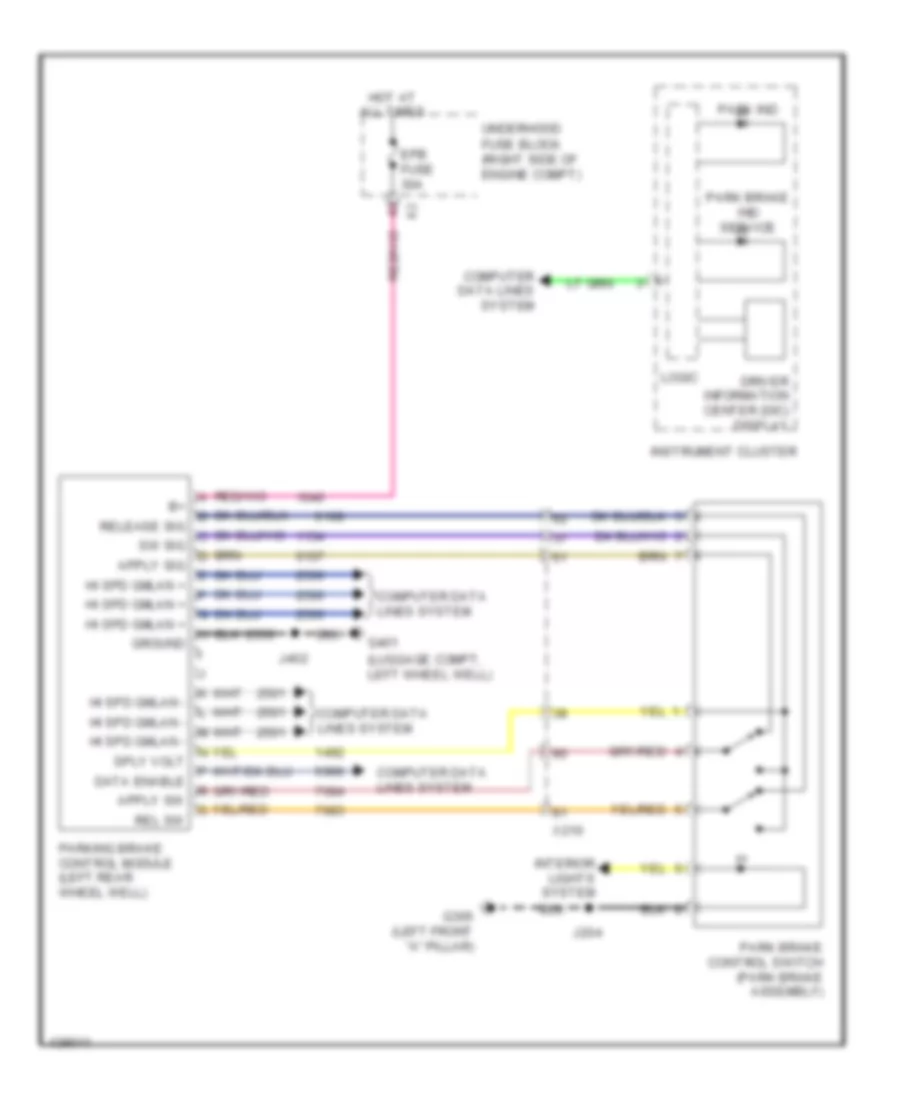
Park Brake System Wiring Diagram for Chevrolet Impala LT 2014
List of elements for Park Brake System Wiring Diagram for Chevrolet Impala LT 2014:
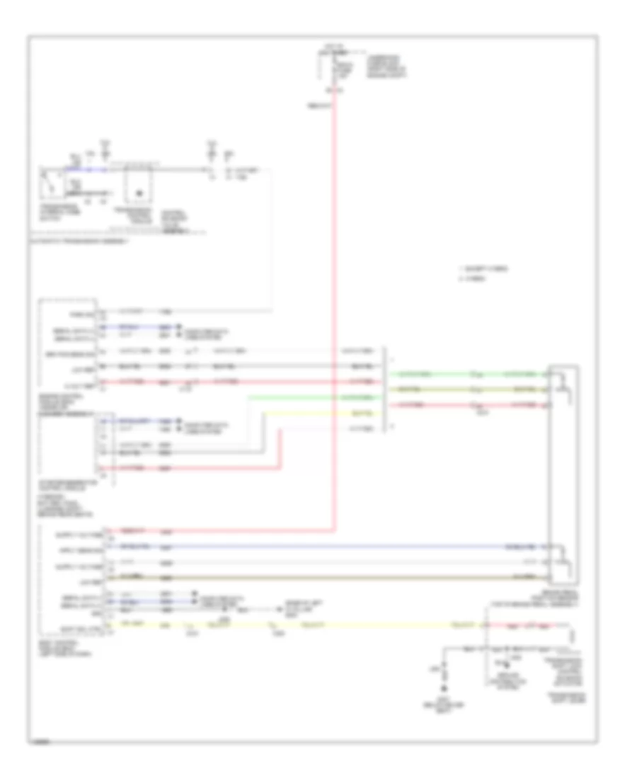
Shift Interlock Wiring Diagram for Chevrolet Impala LT 2014
List of elements for Shift Interlock Wiring Diagram for Chevrolet Impala LT 2014: