POWER DISTRIBUTION
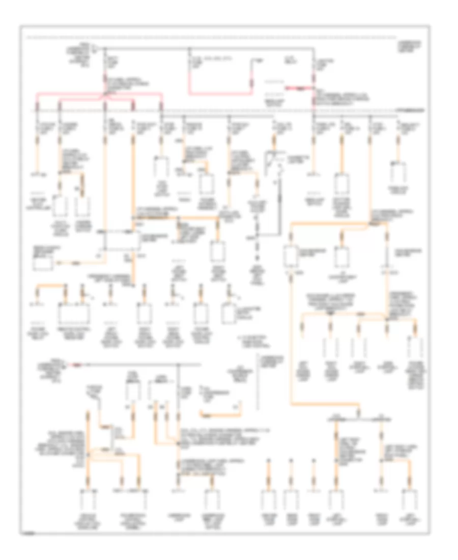
Power Distribution Wiring Diagram (1 of 5) for Chevrolet Chevy Express G2500 2000

List of elements for Power Distribution Wiring Diagram (1 of 5) for Chevrolet Chevy Express G2500 2000:
- (crossbody harness, approx 4 cm from convenience center conn breakout)
- (engine harn, top of engine)
- (i/p harness, approx 4 cm into tcc/stoplamp switch breakout)
- (rear a/c harn, approx 23 cm from blower motor resistor/ relay breakout) s412
- (rear a/c harness, approx 7 cm from blower motor resistor breakout)
- (rear aux htr and a/c harness, approx 29 cm from rear aux hvac module breakout)
- A13
- Abs fuse 60a
- Acc
- Ambulance
- Aux-a fuse 50a
- Aux-b fuse 50a
- Auxiliary battery
- Auxiliary blower motor high speed relay
- Auxiliary blower motor low speed relay
- Auxiliary blower motor medium speed relay
- Battery
- Battery junction block
- Blower fuse 60a
- Blower motor resistor relay
- Brake fuse 18 10a
- C202
- C206
- C210
- C302
- Convenience center
- Crank fuse 8 10a
- Cruise control module (gasoline)
- Cruise control switch
- Cruise fuse 6 10a
- Diesel
- Electronic brake control module (ebcm)
- From aux-a fuse (diagram 1 of 5)
- Front auxiliary hvac control module
- Fusible link (10 ga- rust)
- Fusible link (10 ga-rust)
- G200 (behind left kick panel)
- Gasoline
- Generator
- Glowplug relay
- Heater & a/c controller
- Heater & a/c control logic module
- Htr a/c fuse 12 20a
- I/p fuse block
- Ign-a fuse 40a
- Ign-b fuse 50a
- Ignition switch
- Left front power side window switch
- Lock
- Nca
- Off
- P/b booster fluid low alarm
- Park/ neutral position switch
- Passenger
- Pnk
- Pwr wdo fuse b 25a
- Radio
- Radio 1 fuse 17 10a
- Rear auxiliary hvac control module
- Rear auxiliary mode valve and seal assembly
- Rear auxiliary temperature valve assembly
- Red
- Resistor
- Right front power side window switch
- Rr blower fuse 30a
- Rr hvac fuse 24 10a
- Run
- S122
- S201
- S210
- S213
- S220
- S229
- S252
- S307
- S311
- S312
- S404
- S405
- Start
- Starter relay
- Starter solenoid
- Tcc/ stoplamp switch
- Temperature valve actuator motor
- To s214 (diagram 3 of 5)
- To trans fuse (diagram 4 of 5)
- To underhood fuse-relay center (diagram 2 of 5)
- To upfitter provision relay (diagram 1 of 5)
- Underhood fuse/relay center
- Upfitter provision connector
- Upfitter provision relay (behind left b pillar)
- Vehicle control module (vcm) (gasoline)
- W/ rear a/c
- Windshield washer/ wiper switch
- Windshield wiper motor
- Wiper fuse 11 25a
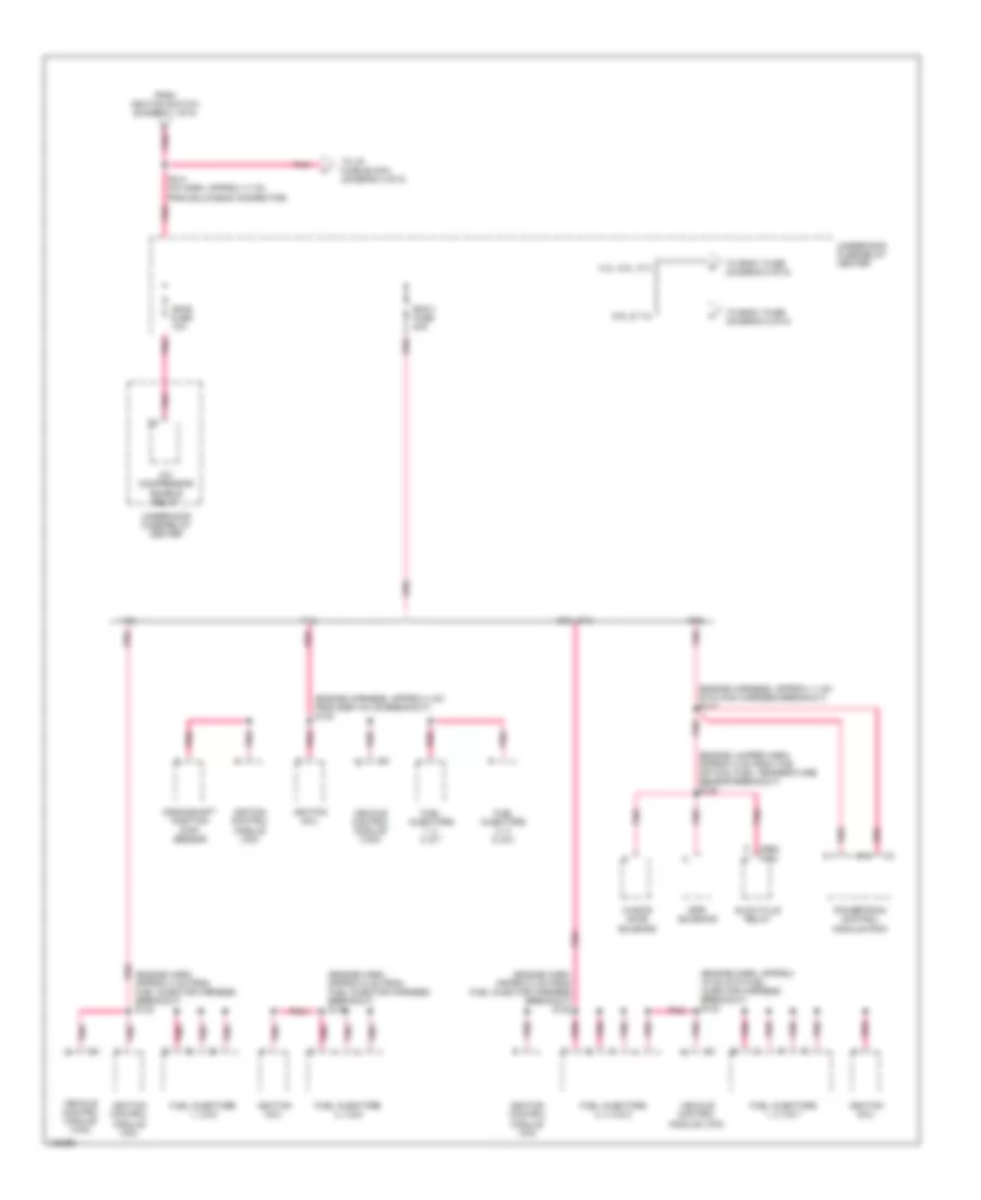
Power Distribution Wiring Diagram (2 of 5) for Chevrolet Chevy Express G2500 2000
List of elements for Power Distribution Wiring Diagram (2 of 5) for Chevrolet Chevy Express G2500 2000:
- (4.3l, 5.0l, 5.7l)
- (6.5l, 5.0l, 5.7l: engine harness, approx 11-19 cm from bulkhead connector, 4.3l, 7.4l: engine harness, approx 65cm from underhood fuse relay center) s127
- (6.5l: engine harn, approx 4 cm into into main harness breakout, 4.3l: engine harn, approx 19 cm from bulkhaed connector) s120 (4.3l & 6.5l)
- (crossbody harn, approx 14 cm from power door lock relay breakout) s232
- (crossbody harness, left side of dash) s228
- (i/p harn, 4 cm from radio breakout) s219
- (i/p harn, 7 cm from instrument cluster breakout) s218
- (i/p harn, approx 37 cm from bulkhead connector) s212
- (i/p harn, approx 8 cm into i/p relay center breakout) s222
- (i/p harness, approx 4 cm into power seat breakout)
- (i/p harness, approx 9 cm from radio breakout) s227
- (left body harn, 150 cm from convenience center connector s406
- (left body harn, left interior roof panel) s406
- (sun shade illum mirror harness, approx 7 cm from right sun shade lamp breakout) s308
- (underhood lamp harn, approx 11 cm from reel lamp connector breakout) s148
- (w/ lamp option)
- 4.3l & 6.5l
- 5.0l, 5.7l, & 7.4l
- A.i.r. fuse 30a
- A.i.r. relay
- A/c compressor enable relay
- A/c compressor fuse 10a
- Auxiliary power outlet
- Batt fuse 50a
- C13
- C202
- C210
- Center dome lamp
- Cig ltr fuse 13 20a
- Cigarette lighter
- Convenience center
- Ctsy fuse 3 20a
- D13
- Data link connector (dlc)
- Daytime running lamp (drl) diode module
- Drl fuse 15 15a
- Ecm-b fuse 20a
- From underhood b fuse-relay center (diagram 1 of 5)
- From underhood fuse-relay center (diagram 1 of 5)
- Front dome lamp
- Fuel pump relay
- G200 (behind left kick panel)
- Hazard fuse 5 20a
- Hazard warning switch
- Headlamp switch
- Heater & a/c controller
- Horn fuse 20a
- Horn relay
- Htd mir fuse 2 20a
- I/p compartment lamp
- I/p fuse block
- Illuminated entry module
- Left front power door lock switch
- Left power seat switch
- Left stepwell lamp
- Left sun shade mirror lamp
- Lighting fuse 40a
- Multi- function alarm module
- Park lps fuse 9 20a
- Passlock module
- Power antenna assembly
- Power door lock control module
- Power door lock relay
- Power outside rear view mirror remote control switch
- Powertrain control module (pcm) (diesel)
- Pwr accy fuse a 25a
- Pwr aux fuse 7 25a
- Radio
- Radio-b fuse 19 10a
- Rear dome lamp
- Rear window defogger relay
- Red
- Remote control door lock receiver
- Right front power door lock switch
- Right power seat switch
- Right rear power door lock switch
- Right stepwell lamp
- Right sun shade mirror lamp
- Rr defog fuse 22 25a
- S205
- S211 (i/p harness, approx 4 cm from park brake warning switch breakout)
- S221
- Security fuse 21 10a
- Side door lock control
- Side stepwell lamp
- Stop fuse 1 20a
- Tcc/ stop- lamp switch
- Underhood fuse/relay center
- Underhood lamp
- Underhood reel lamp (w/ lamp option)
- Vehicle control module (vcm) (gasoline)
- W/ electric a
- W/ upfitter
- W/o upfitter
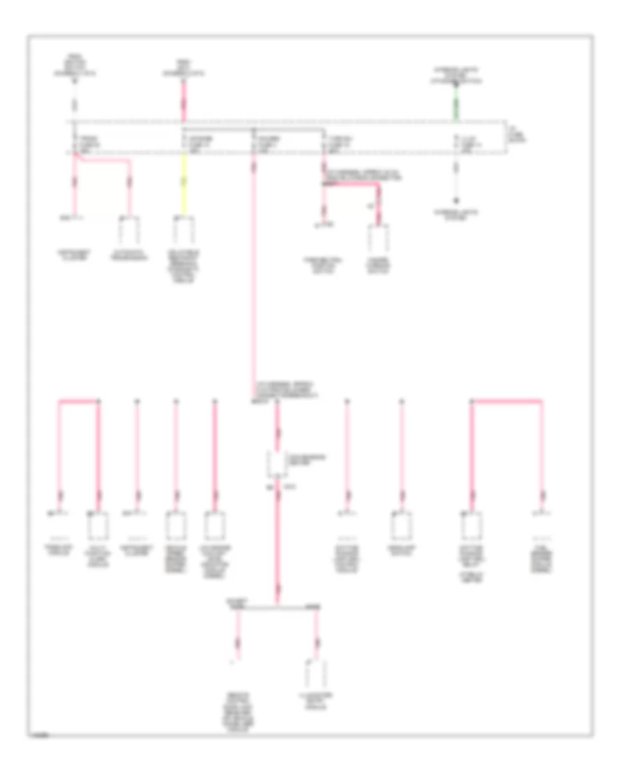
Power Distribution Wiring Diagram (3 of 5) for Chevrolet Chevy Express G2500 2000
List of elements for Power Distribution Wiring Diagram (3 of 5) for Chevrolet Chevy Express G2500 2000:
- (engine harn, approx 15 cm into fuel injector harness breakout) s133
- (engine harn, approx 4 cm from fuel injector harness breakout) s132
- (engine harn, approx 8 cm from fuel injector harness breakout) s132
- (engine harn, approx 8 cm from fuel injector harness breakout) s133
- (engine harness, approx 11 cm into main harness breakout) s117
- (engine harness, approx 4 cm from egr valve breakout) s132
- (engine jumper harn, approx 2 cm from the optical fuel temperature sensor breakout) s108
- (fed) (cal)
- 4.3l
- 4.3l, 5.0l, 5.7l
- 5.0l, 5.7l
- 6.5l
- 6.5l & 7.4l
- 7.4l
- A/c compressor enable relay
- C11
- C12
- Crankshaft position (ckp) sensor
- Ecm-1 fuse 20a
- Epr solenoid
- From ignition switch (diagram 1 of 5)
- Fuel injectors 1, 3 & 5
- Fuel injectors 1, 3, 5 & 7
- Fuel injectors 1, 3, 5, & 7
- Fuel injectors 2, 4 & 6
- Fuel injectors 2, 4, 6 & 8
- Fuel injectors 2, 4, 6, & 8
- Glow plug relay
- Ign-e fuse 10a
- Ignition coil
- Ignition control module (icm)
- Pnk
- Powertrain control module (pcm)
- S214 (i/p harn, approx 17 cm from bulkhead connector)
- To eng-1 fuse (diagram 5 of 5)
- To i/p fuse block (diagram 4 of 5)
- Underhood fuse/relay center
- Vehicle control module (vcm)
- Waste gate solenoid
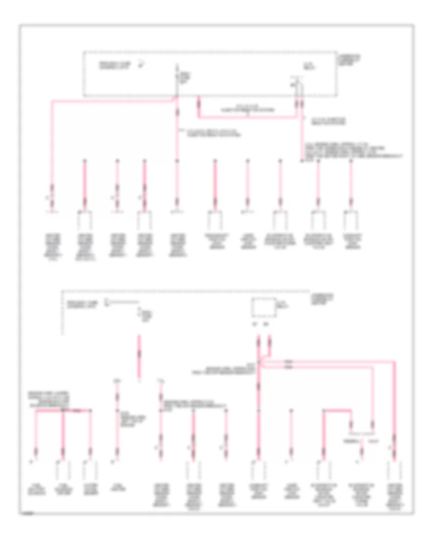
Power Distribution Wiring Diagram (4 of 5) for Chevrolet Chevy Express G2500 2000
List of elements for Power Distribution Wiring Diagram (4 of 5) for Chevrolet Chevy Express G2500 2000:
- (i/p harness, approx 30 cm from bulkhead connector) s217
- (i/p harness, approx 8 cm from bulkhead connector breakout) s216
- Air bags fuse 10 10a
- Automatic transmission
- B10
- B17
- Base
- C210
- Convenience center
- Daytime running lamp (drl) control module
- Daytime running lamp (drl) relay
- Except base
- From ignition switch (diagram 1 of 5)
- From s214 (diagram 3 of 5)
- Fuel sender buffer module (diesel)
- Gauges fuse 4 10a
- Hazard warning switch
- Headlamp switch
- I/p fuse block
- I/p relay center
- Illum fuse 14 10a
- Illuminated entry module
- Inflatable restraint sensing & diagnositc control module
- Instrument cluster
- Interior lights system
- Interior lights system (i/p dimmer switch)
- Low engine coolant level indicator module (diesel)
- Multi- function alarm module
- Park/neutral position switch
- Passlock module
- Pnk
- Remote control door lock receiver or vehicle immobilizer module
- Trans fuse 20 10a
- Turn b/u fuse 16 20a
- Vehicle speed sensor buffer (diesel)
Power Distribution Wiring Diagram (5 of 5) for Chevrolet Chevy Express G2500 2000
List of elements for Power Distribution Wiring Diagram (5 of 5) for Chevrolet Chevy Express G2500 2000:
- (4.3l: engine harn, approx 117 cm from the underhood fuse/relay center, 5.0l & 5.7l: engine harn, approx 12 cm from the heated right oxygen sensor breakout) s130
- (engine harn jumper, approx 4 cm into the engine shutoff solenoid breakout) s107
- (engine harn, approx 5 cm from the ckp sensor breakout) s130
- 4.3l & 5.0l or 5.7l w/o a.i.r. injection reaction system
- 5.7l w/ a.i.r. injection reaction system
- 6.5l
- 7.4l
- A.i.r. relay
- Calif
- Camshaft position (cmp) sensor
- Crankshaft position (ckp) sensor
- Eng-1 fuse 20a
- Evaporative emission (evap) canister purge valve
- Evaporative emission (evap) canister vent valve
- Evaporative emission (evap) canister vent valve (calif)
- Federal
- From ecm-1 fuse (diagram 3 of 5)
- Fuel heater
- Fuel shutoff solenoid
- Fuel solenoid driver
- Heated oxygen sensor (ho2s) bank 1 sensor 1
- Heated oxygen sensor (ho2s) bank 1 sensor 3 (4.3l)
- Heated oxygen sensor (ho2s) bank 1 sensor 3 (5.0l & 5.7l)
- Heated oxygen sensor (ho2s) bank 1 sensor 3 (calif)
- Heated oxygen sensor (ho2s) bank 2 sensor 1
- Heated oxygen sensor (ho2s) bank 2 sensor 1 (calif)
- Heated oxygen sensor (ho2s) bank 2 sensor 2
- Mass airflow (maf) sensor
- Pnk
- S130 (engine harn, left top of engine)
- S131 (engine harn, approx 6cm from the map sensor breakout)
- Underhood fuse/relay center
- W/ a.i.r. injection reaction system
- Water- in-fuel sensor