SHIFT INTERLOCK
Park Brake Release Wiring Diagram, Late Production for Volvo V70 2008

List of elements for Park Brake Release Wiring Diagram, Late Production for Volvo V70 2008:
- (under driver's door sill)
- Central electronic module (behind right end of dash)
- Computer data lines system
- Fuse b11 30a
- Fuse b12 30a
- G47 (at left rear of luggage compt)
- G83
- Hot at all times
- Left rear brake disc lock motor (at left rear brake assembly)
- Parking brake module (pbm) (left side of trunk)
- Parking brake switch
- Rear electrical center (left rear of luggage compt)
- Right rear brake disc lock motor (at right rear brake assembly)
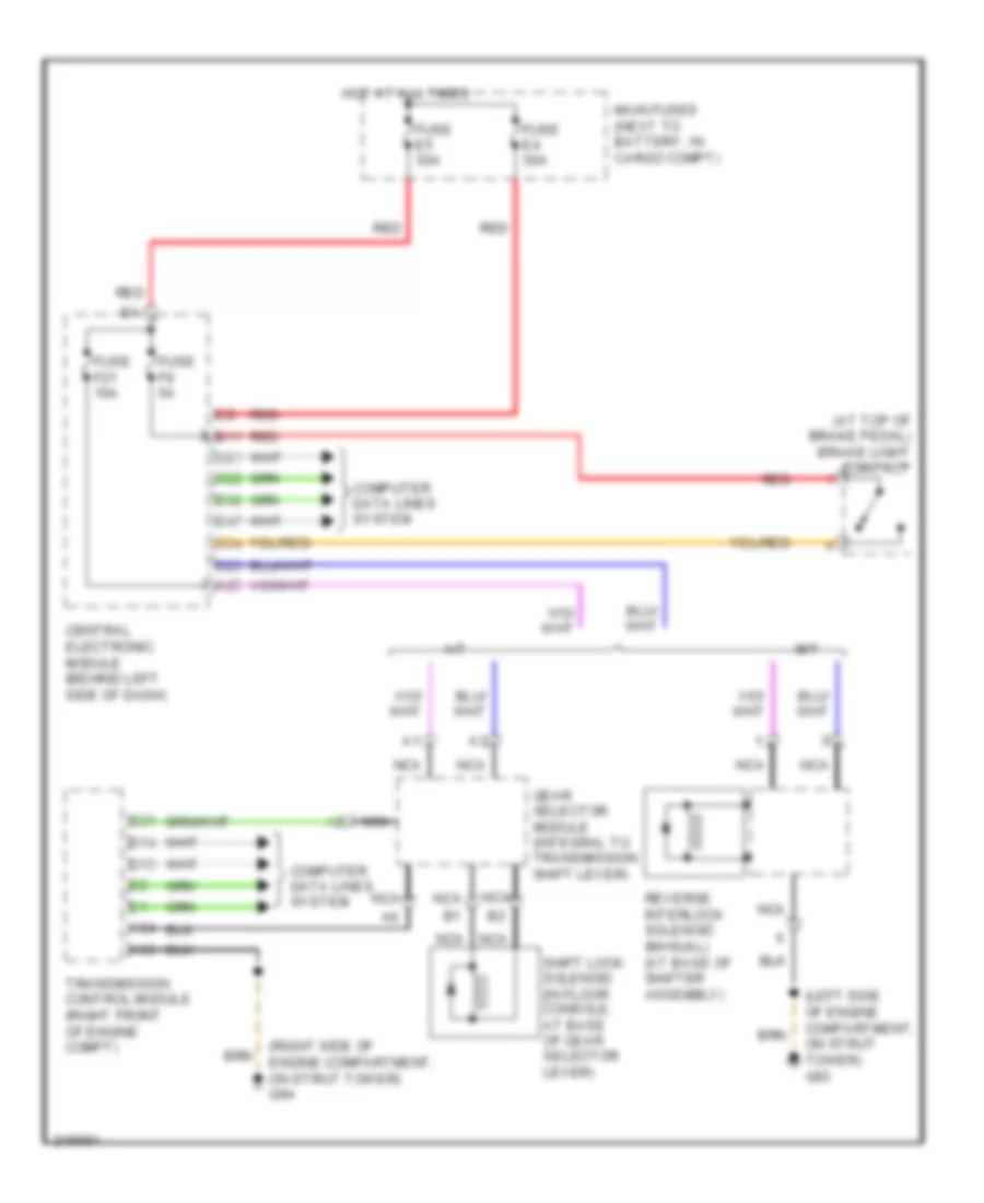
Shift Interlock Wiring Diagram, Early Production for Volvo V70 2008
List of elements for Shift Interlock Wiring Diagram, Early Production for Volvo V70 2008:
- (at top of brake pedal) brake light contact
- (left side of engine compartment, on strut tower) g93
- (right side of engine compartment, on strut tower) g94
- A/t
- A25
- A53
- A54
- B11
- B13
- B14
- B21
- C21
- C22
- C34
- Central electronic module (behind left side of dash)
- Computer data lines system
- D23
- D32
- D47
- Fuse e4 50a
- Fuse e5 50a
- Fuse f21 10a
- Fuse f9 5a
- Gear selector module (integral to transmission shift lever)
- Hot at all times
- M/t
- Main fuses (next to battery, in cargo compt)
- Nca
- Red
- Reverse interlock solenoid (manual) (at base of shifter assembly)
- Shift lock solenoid (in floor console, at base of gear selector lever)
- Transmission control module (right front of engine compt)
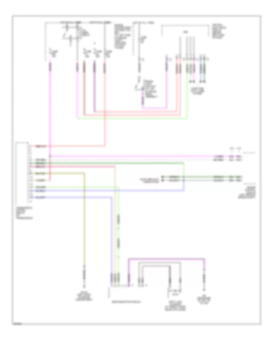
Shift Interlock Wiring Diagram, Late Production for Volvo V70 2008
List of elements for Shift Interlock Wiring Diagram, Late Production for Volvo V70 2008:
- 15- feed relay
- 3.2l
- 4.4l
- B13
- B15
- B30
- B41
- B45
- B54
- B58
- Brake light contact (at top of brake pedal assembly)
- Cem
- Central electronic module (behind right end of dash)
- Computer data lines system
- Engine compartment distribution box (at left side of engine compt, forward of strut tower)
- Engine control module (left rear of engine compt)
- Fuse a1 50a
- Fuse a2 50a
- Fuse b20 10a
- Fuse b31 15a
- Fuse f28 5a
- G6 (near base of left "b" pillar)
- Gear selector module
- Gxx10 (left front of engine compartment)
- Hot at all times
- Nca
- Shift lock solenoid (at base of gear selector lever)
- Transmission control module (on transmission)