TRANSMISSION
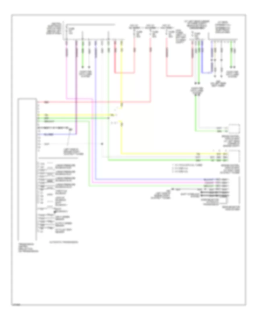
Transmission Wiring Diagram, Early Production 5 Speed A/T for Volvo V70 2008

List of elements for Transmission Wiring Diagram, Early Production 5 Speed A/T for Volvo V70 2008:
- (at left rear corner of cargo compt) rear electronic module (rem)
- (at left rear corner of engine compt)
- (at rear
- (at right front of engine compt) transmission control module (tcm)
- (in engine compt) engine control module (ecm)
- (right side of engine compt, on strut tower)
- A10
- A11
- A12
- A13
- A14
- A15
- A16
- A17
- A18
- A19
- A20
- A21
- A22
- A23
- A24
- A25
- A26
- A27
- A28
- A29
- A30
- A31
- A32
- A33
- A34
- A35
- A36
- A37
- A38
- A39
- A40
- A41
- A42
- A43
- A44
- A45
- A46
- A47
- A48
- A49
- A50
- A51
- A52
- A53
- A54
- A55
- A56
- A57
- A58
- A59
- A60
- A61
- A62
- A63
- A64
- A65
- A66
- A67
- A68
- A69
- A70
- Automatic transmission
- B10
- B11
- B12
- B13
- B14
- B15
- B16
- B17
- B18
- B19
- B20
- B21
- Brake control module (bcm)
- C13
- C14
- C21
- C22
- C28
- Central electronic module (cem) (behind left side of dash)
- Computer data lines system
- D23
- D32
- D47
- Differential electronic module (dem)
- Differential)
- Fuse e1 60a
- Fuse e5 50a
- Fuse f21 10a
- Fuse f23 7.5a
- G46 (on left rear seat riser)
- G93 (left side of engine compt, on strut tower)
- G94
- Gear selector contacts
- Gear selector module (gsm)
- Gear shifting solenoid 1
- Gear shifting solenoid 2
- Hot at all times
- Input speed sensor
- Lock-up solenoid
- Main fuses (next to battery, in cargo compt)
- Mode selector automatic transmission
- Nc1+
- Nc1-
- Nca
- Oil temperature sensor
- Otg
- Output speed sensor
- Pressure solenoid
- Red
- Shift interlock system
- Shift solenoid 3
- Shift solenoid 4
- Shift solenoid 5
- Sls
- Slsg
- Slt
- Sltg
- Slu
- Slug
- Sp+
- Sp-
- St+
- St-
- Throttle solenoid
- Transmission control module (tcm)
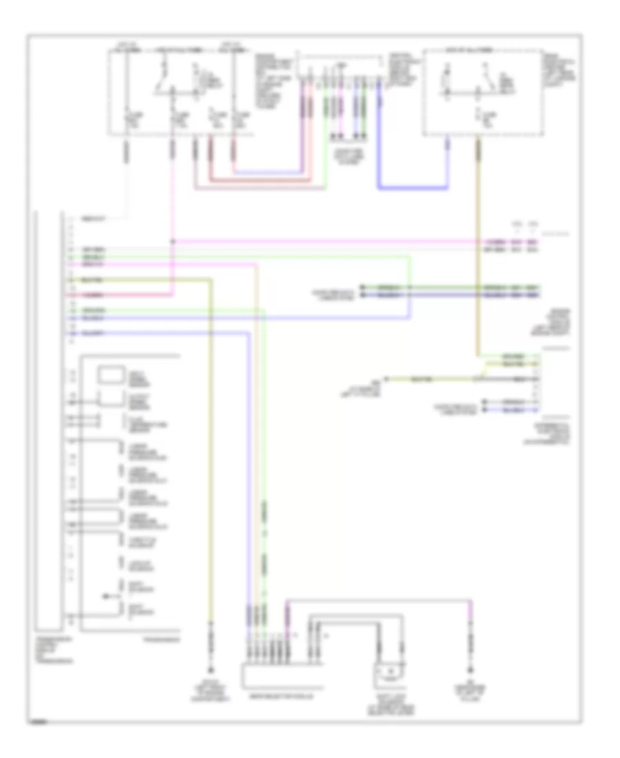
Transmission Wiring Diagram, Early Production 6 Speed A/T for Volvo V70 2008
List of elements for Transmission Wiring Diagram, Early Production 6 Speed A/T for Volvo V70 2008:
- (at left rear corner of cargo compt) rear electronic module (rem)
- (at rear
- (left side of engine compt, on strut tower)
- A/t fluid temp sensor
- A14
- A23
- Automatic transmission
- B13
- B15
- B41
- B45
- B54
- B58
- Brake control module (bcm) (at left rear corner of engine compt)
- C10
- C11
- C12
- C13
- C14
- C16
- C17
- C18
- C19
- C20
- C21
- C22
- C28
- Central electronic module (cem) (behind left side of dash)
- Computer data lines system
- D23
- D32
- D47
- Differential electronic module (dem)
- Differential)
- Engine control module (ecm) (at right side of strut tower)
- Fuse b8 60a
- Fuse e1 60a
- Fuse e5 50a
- Fuse f21 10a
- Fuse f23 7.5a
- G46 (on left rear seat riser)
- G93
- G93 (left side of engine compt, on strut tower)
- Gear selector module (gsm)
- Hot at all times
- Input speed sensor
- Linear pressure solenoid slb1
- Linear pressure solenoid slc1
- Linear pressure solenoid slc2
- Linear pressure solenoid slc3
- Lock-up solenoid
- Main fuses (next to battery, in cargo compt)
- Mode selector automatic transmission
- Nca
- Output speed sensor
- Red
- Shift interlock system
- Shift solenoid 1
- Shift solenoid 2
- Throttle solenoid
- Transmission control module (tcm) (on transmission)
- W/ v70 & xc70 2.5l turbo
- W/ xc90 3.2l
- W/ xc90 4.4l
Transmission Wiring Diagram, Late Production for Volvo V70 2008
List of elements for Transmission Wiring Diagram, Late Production for Volvo V70 2008:
- 15- feed rear relay
- 15- feed relay
- 3.2l
- 4.4l
- B13
- B15
- B30
- B41
- B45
- B54
- B58
- Cem
- Central electronic module (behind right end of dash) c2
- Computer data lines system
- Differential electronic module (on differential)
- Engine compartment distribution box (at left side of engine compt, forward of strut tower)
- Engine control module (left rear of engine compt)
- Fluid temperature sensor
- Fuse a1 60a
- Fuse a2 60a
- Fuse b20 7.5a
- Fuse b31 15a
- Fuse b6 10a
- G6 (near base of left "b" pillar)
- G65 (at base of left "c" pillar)
- Gear selector module
- Gxx10 (left front of engine compartment)
- Hot at all times
- Input speed sensor
- Linear pressure solenoid slb1
- Linear pressure solenoid slc1
- Linear pressure solenoid slc2
- Linear pressure solenoid slc3
- Lock-up solenoid
- Nca
- Output speed sensor
- Rear electrical center (left rear of luggage compt)
- Shift lock solenoid (at base of gear selector lever)
- Shift solenoid
- Throttle solenoid
- Transmission
- Transmission control module (on transmission)