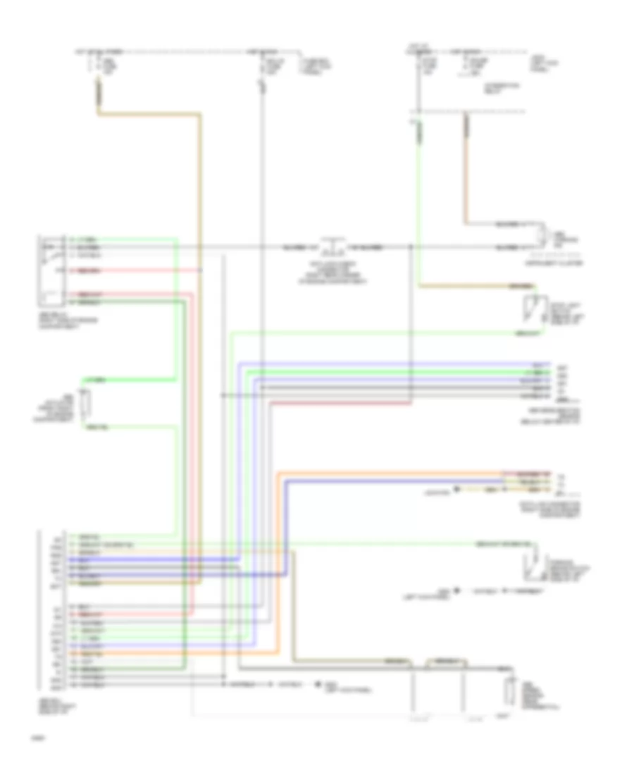
AUTOMOTIVE ELECTRICIANS PORTAL

ANTI-LOCK BRAKES – Toyota 4Runner SR5 1994 – SYSTEM WIRING DIAGRAMS

ANTI-LOCK BRAKES

All-Wheel ABS Wiring Diagram for Toyota 4Runner SR5 1994

All-Wheel ABS Wiring Diagram for Toyota 4Runner SR5 1994 https://portal-diagnostov.com/license.html
https://portal-diagnostov.com/license.html Automotive Electricians Portal FZCO Automotive Electricians Portal FZCO
Download PDF file

List of elements for All-Wheel ABS Wiring Diagram for Toyota 4Runner SR5 1994:

  • A10
  • A11
  • A12
  • A13
  • A14
  • A15
  • A16
  • A17
  • A18
  • A19
  • A20
  • A21
  • A22
  • A23
  • A24
  • A25
  • A26
  • Abs actuator (left side of engine compartment)
  • Abs check connector (right rear of engine compartment)
  • Abs deceleration sensor (under right front seat)
  • Abs ecu (below center of i/p)
  • Abs fuse 60a
  • Abs relay (left side of engine compartment)
  • Abs warning ind
  • Add switch
  • Ast
  • B10
  • B11
  • B12
  • B13
  • B14
  • B15
  • B16
  • Bat
  • Brake fluid level switch (brake fluid reservoir)
  • Data link connector 1 (right rear corner of engine compartment)
  • Dome fuse 15a
  • Ecu-ig fuse 20a
  • Ex1
  • Fl+
  • Fl-
  • Fr+
  • Fr-
  • Fss
  • Fuse block (attatched to j/b #1) (left kick panel)
  • Fuse box (r/b #2) (right side of engine compartment)
  • G117 (right rear of engine)
  • G200 (left kick panel)
  • Gauge fuse 10a
  • Ggnd
  • Gnd
  • Gs1
  • Gs2
  • Gst
  • Hot at all times
  • Hot in run
  • Ig1
  • Instrument cluster
  • Integration relay
  • J/b #1 (left kick panel)
  • Left front abs speed sensor
  • Left rear abs speed sensor
  • Nca
  • Parking brake switch (under front center of passenger compartment)
  • Pkb
  • Pnk
  • R/b #2 (right side of engine compartment)
  • Red
  • Right front abs speed sensor
  • Right rear abs speed sensor
  • Rl+
  • Rl-
  • Rr+
  • Rr-
  • Rss
  • Sflh
  • Sflr
  • Sfrh
  • Sfrr
  • Srh
  • Srr
  • Stop fuse 15a
  • Stop light switch (behind left side of i/p)
  • Stp

Rear ABS Wiring Diagram for Toyota 4Runner SR5 1994

Rear ABS Wiring Diagram for Toyota 4Runner SR5 1994 https://portal-diagnostov.com/license.html
https://portal-diagnostov.com/license.html Automotive Electricians Portal FZCO Automotive Electricians Portal FZCO
Get access to all wiring diagrams of the carDownload PDF file

List of elements for Rear ABS Wiring Diagram for Toyota 4Runner SR5 1994:

  • Abs actuator (front right of engine compartment)
  • Abs deceleration sensor (below center of i/p)
  • Abs ecu (behind right side of i/p)
  • Abs fuse 15a
  • Abs relay (right side of engine compartment)
  • Abs speed sensor (rear differential)
  • Abs warning ind
  • Anti-lock check connector (right rear corner of engine compartment)
  • Bat
  • Data link connector (right side of engine compartment)
  • Ecu-ig fuse 20a
  • Fuse box (left kick panel)
  • G200 (left kick panel)
  • Gauge fuse 10a
  • Gnd
  • Gs1
  • Gs2
  • Gst
  • Hot at all times
  • Hot in run
  • Ig1
  • Instrument cluster
  • Integration relay
  • J/b #1 (left kick panel)
  • Location
  • Parking brake switch (behind left side of i/p)
  • Pkb
  • Rr+
  • Rr-
  • Rss
  • Stop fuse 15a
  • Stop light switch (behind left side of i/p)
  • Stp