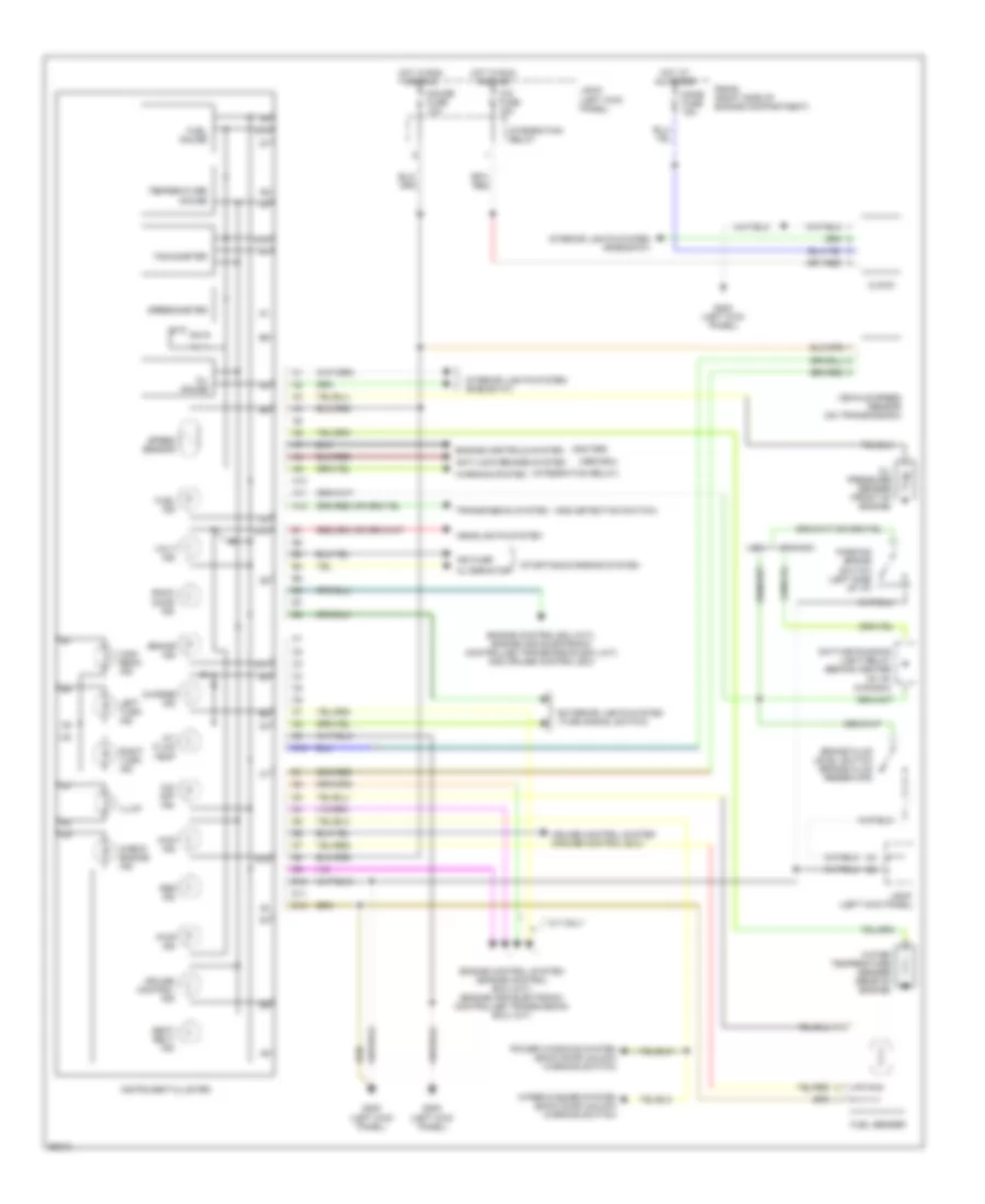
INSTRUMENT CLUSTER
Instrument Cluster Wiring Diagram for Toyota 4Runner SR5 1994
List of elements for Instrument Cluster Wiring Diagram for Toyota 4Runner SR5 1994:
- (abs ecu)
- (add detection switch)
- (igniter)
- (integration relay)
- 4wd ind
- A/t fluid temp
- A/t only
- A10
- A11
- A12
- Abs ind
- Alternator
- Anti-lock brakes system
- Back door ind
- Brake fluid level switch (brake fluid reservoir)
- Brake ind
- C10
- Canada
- Charge ind
- Check engine ind
- Cig fuse 15a
- Clock
- Cruise control ind
- Cruise control system (cruise control ecu)
- D10
- D11
- D12
- Daytime running light relay (behind center of i/p) (canada)
- Dome fuse 15a
- Engine control ecu (m/t), engine and electronic controlled transmission ecu (a/t) and cruise control ecu
- Engine control system (engine control ecu) (m/t) (engine and electronic controlled transmission ecu) (a/t)
- Engine controls system
- Exterior lights system (turn signal switch)
- Fuel gauge
- Fuel ind
- Fuel sender
- G200 (left kick panel)
- Gauge fuse 10a
- Headlights system
- High beam ind
- Hot at all times
- Hot in run and acc
- Ign fuse
- Illum
- Instrument cluster
- Integration relay
- Interior lights system (rheostat)
- J/b #1 (left kick panel)
- Left turn ind
- O/d off ind
- Oil gauge
- Oil pressure sender (front of engine)
- Parking brake switch (left side of i/p)
- Power windows system (back door unlock warning switch)
- Pwr ind
- R/b #2 (right side of engine compartment)
- Right turn ind
- Seat belt ind
- Speed sensor
- Speedometer
- Starting/charging system
- Tachometer
- Temperature gauge
- Transmission system
- Usa
- Vehicle speed sensor (on transmission)
- Volt ind
- Warning system
- Water temperature sender (rear of engine)
- Wiper/washer system (back door unlock warning switch)
 English