TRANSMISSION
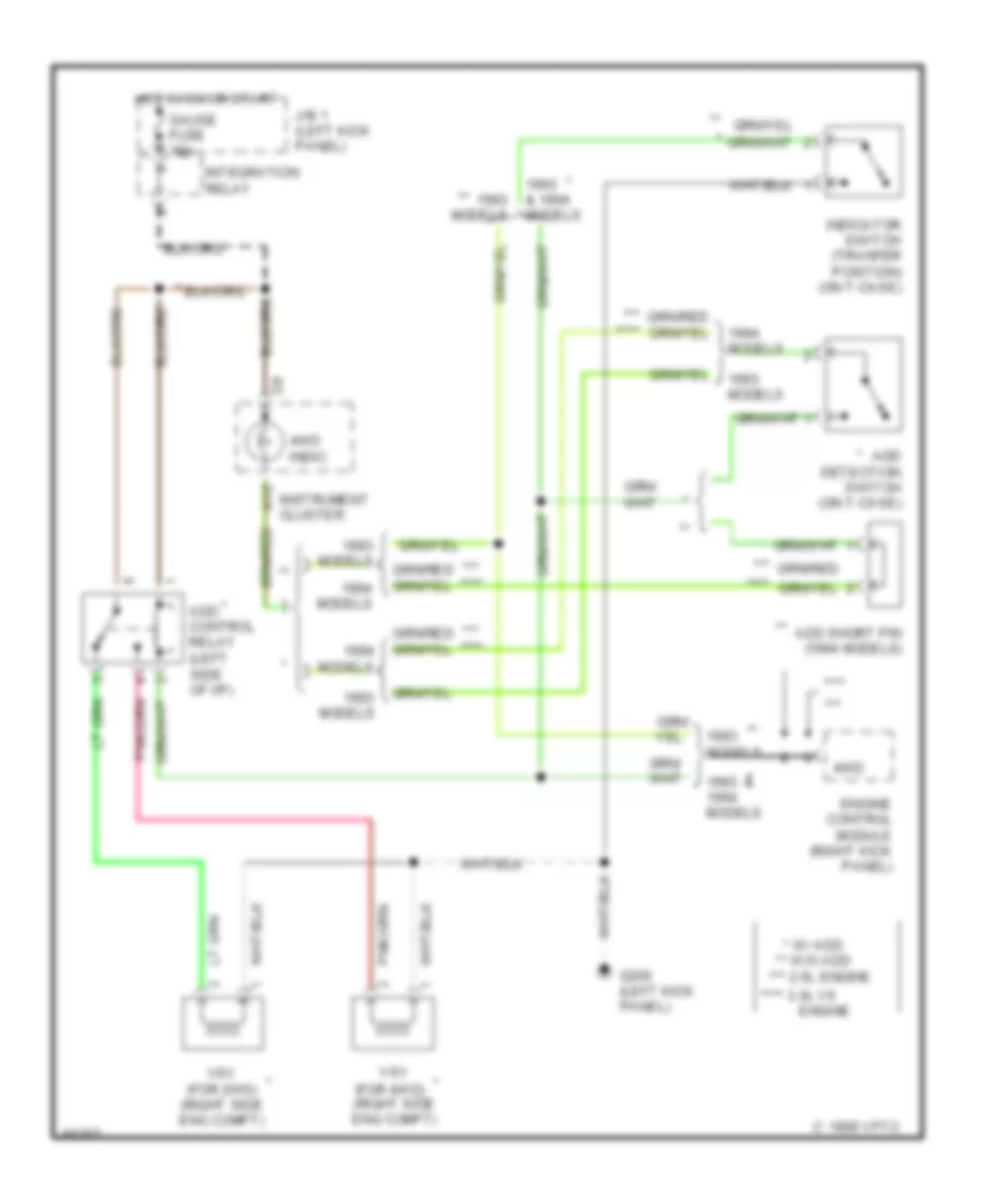
Transfer Case Wiring Diagram, A/T for Toyota 4Runner SR5 1994

List of elements for Transfer Case Wiring Diagram, A/T for Toyota 4Runner SR5 1994:
Transfer Case Wiring Diagram, M/T for Toyota 4Runner SR5 1994
List of elements for Transfer Case Wiring Diagram, M/T for Toyota 4Runner SR5 1994:
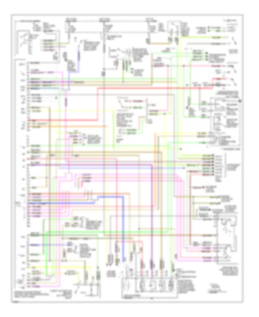
Transmission Wiring Diagram for Toyota 4Runner SR5 1994
List of elements for Transmission Wiring Diagram for Toyota 4Runner SR5 1994: