ANTI-LOCK BRAKES
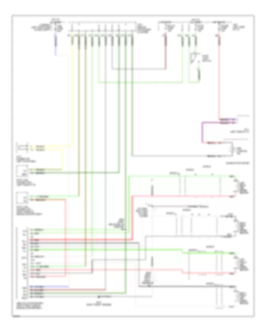
Anti-lock Brake Wiring Diagrams, TMC Made for Toyota Camry SE 1996

List of elements for Anti-lock Brake Wiring Diagrams, TMC Made for Toyota Camry SE 1996:
- (eng harn, above grille opening)
- (i/p harn, behind right side of dash)
- (i/p harn, right end of dash)
- (left front fender) g100
- A10
- A11
- A12
- A13
- A14
- A15
- A16
- A17
- A18
- A19
- A20
- A21
- A22
- A23
- A24
- A25
- A26
- Abs actuator (front right side of engine compartment)
- Abs ecu (tmc made) (above right kick panel)
- Abs fuse 60a
- Abs relay (right front of eng. compt.)
- Abs warning ind
- Ast
- B10
- B11
- B12
- B13
- B14
- B15
- B16
- Bat
- C15
- C16
- C19
- Combination meter
- D/g
- Data link connector 1 (right rear corner of eng compt)
- Data link connector 2 (left side of i/p)
- Ecu-b fuse 15a
- Ecu-ig fuse 15a
- Fl+
- Fl-
- Fr+
- Fr-
- Fss
- Fuse box (left side of eng compt)
- G101 (right front fender)
- Gauge fuse 10a
- Gnd
- Hot at all times
- Hot in run
- I21
- I25
- Ig1
- J/b 1 (left side of i/p)
- J/b 2 (left side of eng compt)
- J/b 3 (behind combination meter)
- J/b 3 (behind instrument cluster)
- J/b 3 (behind instrumnt cluster)
- J/c 1 (left side of i/p)
- J/c 4 (left kick panel)
- Left front abs speed sensor
- Left rear abs speed sensor
- Lever type
- Parking brake switch
- Pedal type
- Pkb
- Red
- Right front abs speed sensor
- Right rear abs speed sensor
- Rl+
- Rl-
- Rr+
- Rr-
- Rrs
- Sfl
- Sfr
- Shield
- Srl
- Srr
- Stop fuse 15a
- Stop light switch
- Stp
Anti-lock Brake Wiring Diagrams, TMM Made for Toyota Camry SE 1996
List of elements for Anti-lock Brake Wiring Diagrams, TMM Made for Toyota Camry SE 1996:
- (eng harn, above grille opening) e4
- (eng harn, right front fender) e1
- (i/p harn, ridht end of dash cover)
- +bs
- A10
- A11
- A12
- A13
- A14
- A15
- Abs
- Abs actuator and ecu (right front side of engine compartment)
- Abs fuse 60a
- Abs warning ind
- Combiniation meter
- Data link connector 1 (right rear of engine compartment)
- Data link connector 2 (left side of i/p)
- Ecu-ig fuse 15a
- Fl+
- Fl-
- Fr+
- Fr-
- Fuse box (left front side of eng compt)
- G101 (right front fender)
- Gauge fuse 10a
- Gnd
- Hot at all times
- Hot in on
- Hot in run
- I21
- Ig1
- J/b 1 (left side of i/p)
- J/b 3 (behind instrument cluster)
- J/c 1 (left side of i/p)
- J/c 4 connector (left kick panel)
- Left front abs speed sensor
- Left rear abs speed sensor
- Red
- Right front abs speed sensor
- Right rear abs speed sensor
- Rl+
- Rl-
- Rr+
- Rr-
- Shield
- Stop fuse 15a
- Stop light switch
- Stp