ENGINE PERFORMANCE
2.2L
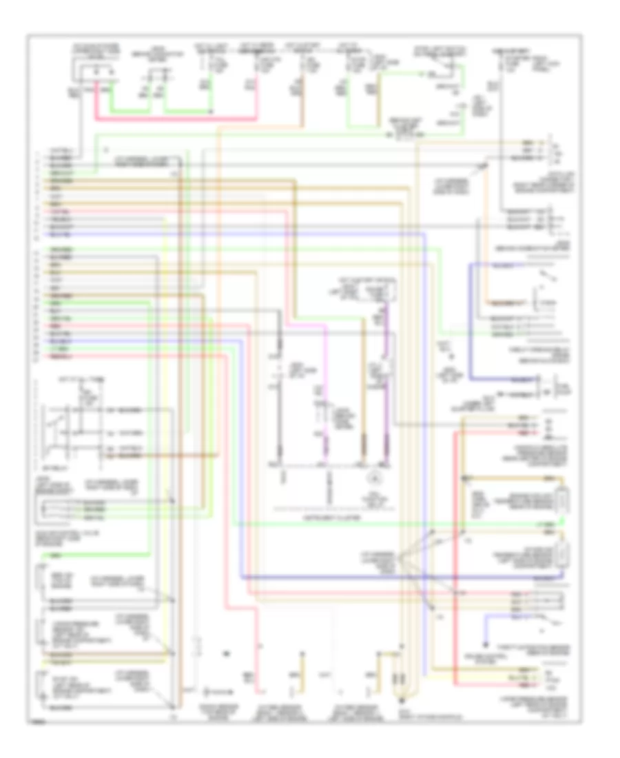
2.2L, Engine Performance Wiring Diagrams (1 of 2) for Toyota Camry SE 1996

List of elements for 2.2L, Engine Performance Wiring Diagrams (1 of 2) for Toyota Camry SE 1996:
- #10
- #20
- #30
- #40
- (engine harness, above injectors 2 & 3)
- (engine harness, right side of engine near strut tower)
- (i/p harn, lower right side of dash)
- (i/p harness, right side of dash)
- (i/p harness, upper left kick panel)
- (left kick panel) g200
- A/c system
- Ac1
- Acc
- Act
- Bat
- Batt
- Canada
- Conn e11
- Conn e12
- Conn e14
- Crankshaft position sensor (front of engine)
- Data link connector 2 (left side of i/p)
- Data link connector 3 (left side of i/p)
- Distributor (rear of engine)
- E01
- E02
- E03
- E15
- E17
- Egr
- Els
- Engine control module (below left side of i/p)
- Evp
- Ex canada
- G131 (left intake manifold)
- G131 (right intake manifold)
- Hot at all times
- I18
- I20
- I23
- Ig-
- Igf
- Igniter (left side of engine compartment)
- Ignition coil (left side of engine compartment)
- Ignition switch
- Igt
- Injector #1
- Injector #2
- Injector #3
- Injector #4
- J/b #1 (left side of i/p)
- J/b #2 (left side of engine compt)
- J/c j1 (left side of dash)
- Knk
- Lock
- Nca
- Ne-
- Noise filter (left side of engine compartment)
- Nsw
- Obd fuse 7.5a
- Od2
- Ox1
- Ox2
- Park/ neutral position switch
- Pim
- Ptnk
- Pwr
- Red
- Rsc
- Rso
- Run
- Sdl
- Spd
- Sta
- Start
- Stp
- Te1
- Tha
- Thw
- Tpc
- Transmission system
- Vta
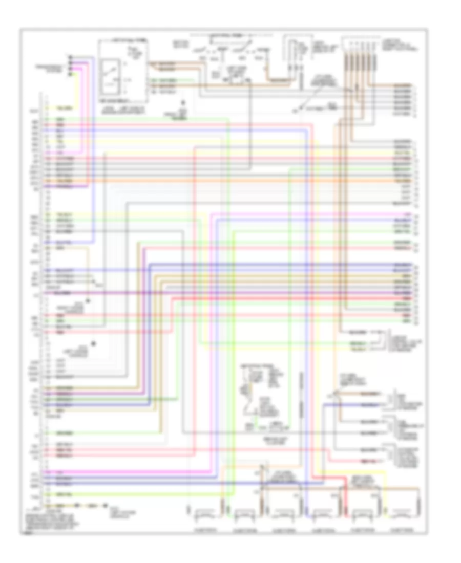
2.2L, Engine Performance Wiring Diagrams (2 of 2) for Toyota Camry SE 1996
List of elements for 2.2L, Engine Performance Wiring Diagrams (2 of 2) for Toyota Camry SE 1996:
- (behind inst cluster) j/b 3
- (eng harn, above inj 2 & 3)
- (i/p harness, lower right side of dash)
- (i/p harness, lower right side of dash) i18
- (i/p harness, lower right side of dash) i27
- A/c idle-up diode (upper right side of i/p)
- A15
- B11
- B20
- Circuit opening relay (r/b #6) (behind glove box)
- Cruise control system
- D10
- D13
- D14
- D14 pnk
- D22
- Data link connector 1 (right rear corner of engine compartment)
- E17
- Efi fuse 15a
- Efi relay
- Egr vsv (top of engine)
- Engine coolant temperature sensor (rear of engine)
- Evap vsv (left rear of engine compartment) (a/t only)
- Fuel pump
- G131 (right intake manifold)
- G202 (left side of i/p)
- G414 (under left quarter pillar)
- Gauge fuse 10a
- Hot at all times
- Hot in start
- Hot in start or run
- Hot w/ light switch on
- Hot w/ rear defogger on
- I18
- Idle air control valve (rear right side of engine)
- Ign fuse 7.5a
- Instrument cluster
- Intake air temperature sensor (left side of engine compartment)
- J/b #1 (left side of i/p)
- J/b #2 (left side of engine compt)
- J/b #3 (behind comb meter)
- J/b #3 (behind combination meter)
- J/b #3 (behind comination meter)
- J/b 1 (left side of dash)
- J/c j1 (left side of b dash)
- Knock sensor (top rear of engine)
- Mal- function ind lp
- Manifold absolute pressure sensor (rear center of engine compartment)
- Mir htr fuse 10a
- Oxygen sensor (bank 1 sensor 1) (left side of engine)
- Oxygen sensor (bank 1 sensor 2) (left side of engine)
- Ptnk
- R/b #1 (left kick panel)
- Red
- Speed input
- Starter fuse 10a
- Stop fuse 15a
- Stop light switch (on pedal support)
- Tach
- Tail fuse 15a
- Te1
- Throttle position sensor (rear of engine)
- Vapor pressure sensor (left rear of engine compartment) (a/t only)
- Vapor pressure sensor vsv (left rear of engine compartment) (a/t only)
- Vcc
3.0L
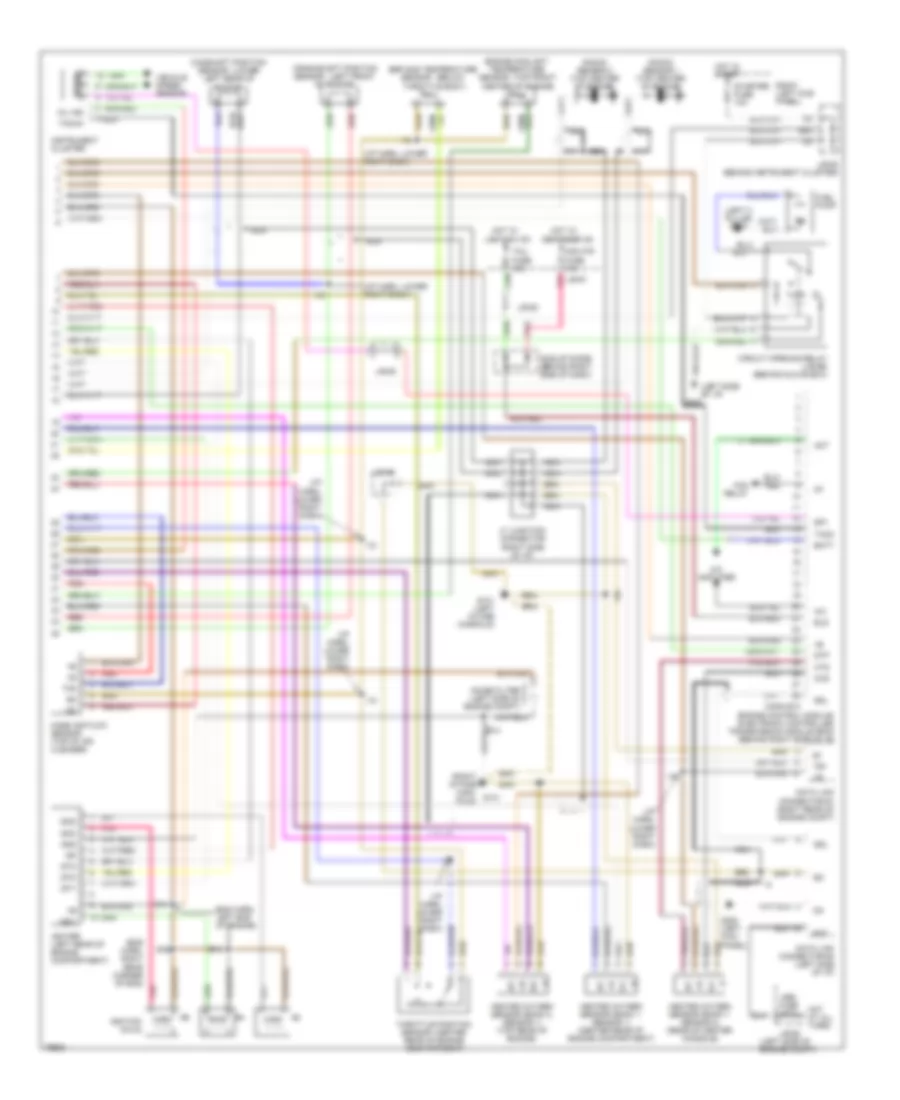
3.0L, Engine Performance Wiring Diagrams (1 of 2) for Toyota Camry SE 1996
List of elements for 3.0L, Engine Performance Wiring Diagrams (1 of 2) for Toyota Camry SE 1996:
- #10
- #20
- #30
- #40
- #50
- #60
- (behind inst cluster)
- (eng harn, left side of firewall)
- (i/p harn, lower right side of dash)
- (left side of
- (left side of dash) j/b 1
- Acc
- Acis
- C19
- Conn e7
- Conn e8
- Conn e9
- E01
- E02
- E03
- E12
- Efi fuse 15a
- Efi main relay
- Egr
- Egr vsv (top center of engine)
- Engine compartment)
- Engine control module/ electronic controlled transmission module (ecm) (behind right side of i/p)
- Fpu
- Fuel pressure up vsv (top rear of engine)
- G100 (front left fender)
- G131 (left intake manifold)
- G131 (right intake manifold)
- G22+
- Hot at all times
- Htl
- Htr
- I18
- I20
- I27
- Idl
- Igf
- Ign fuse 7.5a
- Ignition switch
- Igt1
- Igt2
- Igt3
- Igt5
- Ilde air control valve (top center of engine)
- Injector #1
- Injector #2
- Injector #3
- Injector #4
- Injector #5
- Injector #6
- Intake air control valve vsv (top front of engine)
- J/b #1 (behind left side of i/p)
- J/b #1 (behind left side of i/p)
- J/b #2
- J/b 3
- Junction connector j8 (right kick panel)
- Knkl
- Knkr
- Lock
- Ne+
- Ne-
- Nsw
- Oxl
- Oxr
- Red
- Rsc
- Rso
- Run
- Sln-
- Sta
- Start
- Stop fuse 15a
- Stop light switch (on pedal support)
- Te1
- Tha
- Thg
- Thw
- Transmission system
- Vg-
- Vta
3.0L, Engine Performance Wiring Diagrams (2 of 2) for Toyota Camry SE 1996
List of elements for 3.0L, Engine Performance Wiring Diagrams (2 of 2) for Toyota Camry SE 1996:
- (below
- (center
- (eng harn, right rear corner of eng)
- (i/p harn, lower right dash)
- (left c pillar) g904
- (left front
- (left side of engine compt)
- (left side of i/p)
- (lower
- (right intake mani- fold)
- (right side of i/p)
- (top front
- +b +b
- A/c
- A/c amplifier
- Act
- B20
- Bat
- Batt
- Camshaft position
- Center of engine)
- Circuit opening relay (j/b #6) (behind glove box)
- Conn e10
- Crankshaft position
- Data link connector #1 (right rear of engine compt)
- Data link connector #3 (left side of i/p)
- Defogger on
- E e
- E12
- E14
- Egr gas temperature
- Els
- Eng harn, left end of engine)
- Engine control module/ electronic controlled transmission module (ecm) (behind right side of i/p)
- Engine coolant temperature
- Fan relay
- Fuel pump
- G131
- G131 (left intake manifold)
- G200 (left kick panel)
- G202
- Gnd
- Heated oxygen sensor (bank 1, sensor 1) (center rear of engine compartment)
- Heated oxygen sensor (bank 1, sensor 2) (rear of center console)
- Heated oxygen sensor (bank 2, sensor 1) (top rear of engine)
- Hot at all times
- Hot in start
- Hot w/
- Ht ht
- Hts
- I18
- Idle-up diode (behind right side of dash)
- Igc1
- Igc2
- Igc3
- Igf
- Igniter (left rear of engine compartment)
- Ignition coils
- Igt1
- Igt2
- Igt3
- Instrument cluster
- J/b #1
- J/b #2
- J/b #3
- J/b #3 (behind instrument cluster)
- J7 junction connector
- Knock sensor 1 (top center of engine)
- Knock sensor 2 (top center of engine)
- Left rear of engine)
- Light sw on
- Mass air flow sensor (top of air cleaner)
- Mil ind
- Mir htr fuse 10a
- Nca
- Noise filter (left side of engine compt)
- Obd fuse 7.5a
- Of engine)
- Ox ox
- Oxs
- Pnk
- R/b #1 (left kick panel)
- Rear of engine compartment)
- Red
- Sdl
- Sensor
- Sp1
- Speed
- Starter fuse 10a
- Stp
- Tacho
- Taco
- Tail fuse 15a
- Te1
- Tha
- Throttle body)
- Throttle position
- Vehicle speed sensor
- Vg-