ANTI-LOCK BRAKES
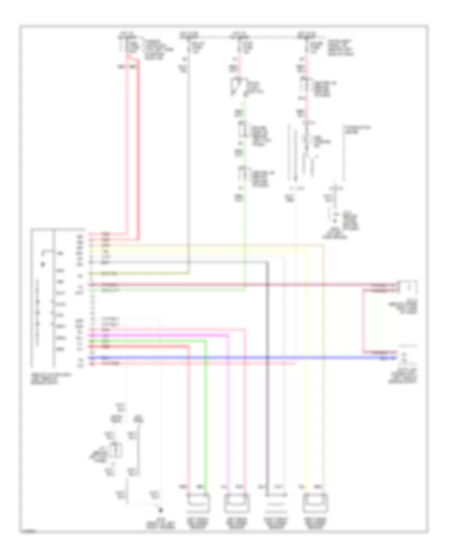
Anti-lock Brake Wiring Diagrams for Toyota Corolla LE 1998
List of elements for Anti-lock Brake Wiring Diagrams for Toyota Corolla LE 1998:
- +bm
- +bs
- Abs actuator & ecu (left rear of engine compt)
- Abs fuse 50a
- Abs warning ind
- B18
- C13
- C14
- Center j/b (behind center of dash)
- Combination meter
- Data link connector 1 (left side of engine compt)
- Driver side j/b (behind left kick panel)
- Ecu-ig fuse 10a
- Fl+
- Fl-
- Fr+
- Fr-
- Fusible link block (top left side of engine room j/b)
- G100 (front of left front fender)
- G205 (on left dash brace)
- Gauge fuse 10a
- Gnd
- Hot at all times
- Hot in on or start
- Ig1
- Instrument panel j/b (behind left side of dash)
- J/c 1 (behind left kick panel)
- J/c 13 (behind upper right side of dash)
- J/c 8 (behind lower center of dash)
- Japan prod
- Left front abs speed sensor
- Left rear abs speed sensor
- Pnk
- Red
- Right front abs speed sensor
- Right rear abs speed sensor
- Rl+
- Rl-
- Rr+
- Rr-
- Slh1
- Slh2
- Slr
- Srh1
- Srh2
- Srr
- Stop fuse 15a
- Stop- light switch
- Stp
- Usa prod
 English